
tcpGPS
Surface tools - GPS v2
13.2 Surface Tools
Pressing the  button will open a map screen with further tools to be able to measure and interact with surfaces.
Measuring
Pressing the  button allows the selection of two points to get the distance between them to help with the tasks by obtaining precise measurement data.
Quick Profile
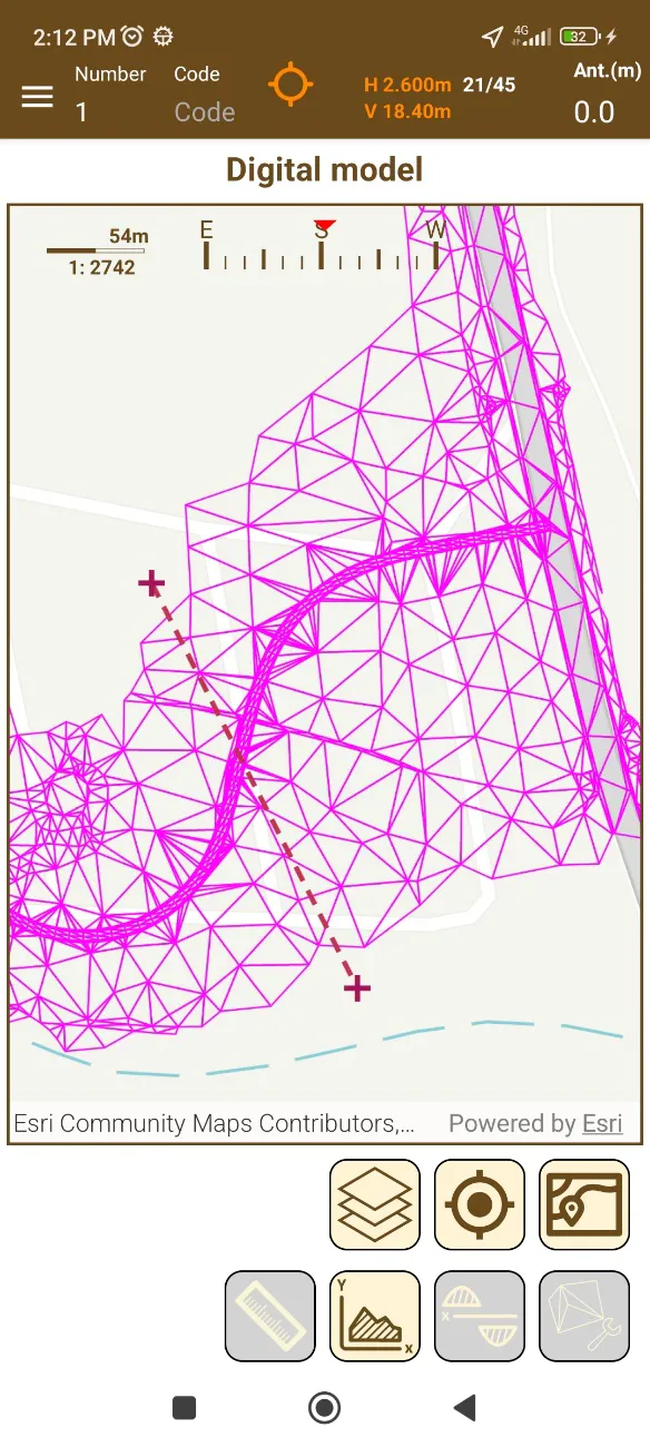
By pressing the button with the icon  located on the Digital Model screen it is possible to quickly make a section between the line that is drawn and the current model, thus showing the profile of this 3D model between said points.
After pressing the button, touch two points on the screen that will be the two ends of the line.
 |
|---|
Figure 116. Drawing the profile line |
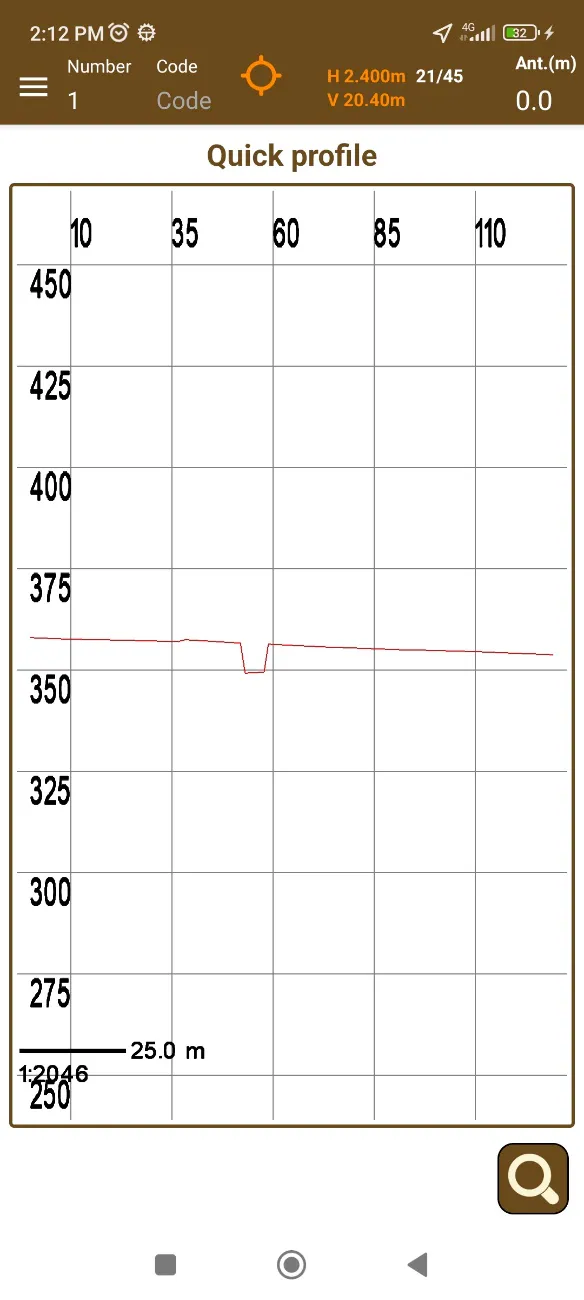
If this line cuts the model, the graph with the level dimensions and its profile between the two points will be displayed on the screen.
 |
|---|
Figure 117. Terrain profile |
Volume Calculation
By pressing the button with the icon  on the Digital Model screen you will enter the volume calculation mode.
In this mode it is possible to determine the volumes of cutting and filling of a chosen esplanade at the level indicated by the user.
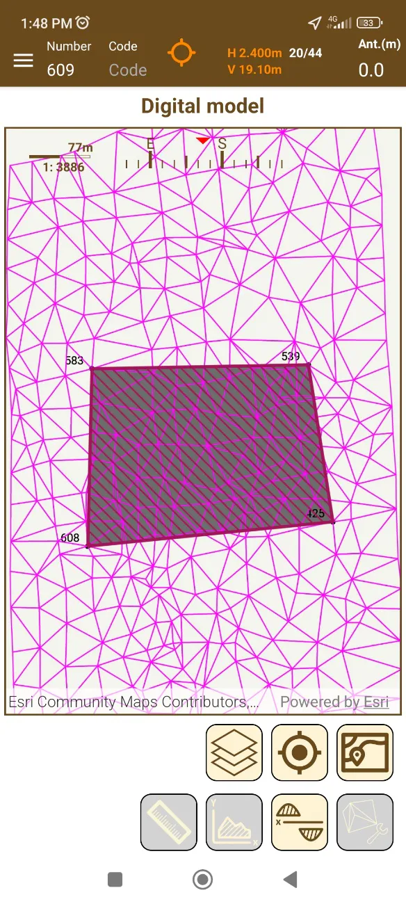
To begin, it is necessary to select a polygon or parcel that is contained in or intersects with the selected model, by clicking on this polygon.
The selected polygon will be shown shaded with lines.
 |
|---|
Figure 118. Polygon as esplanade. |
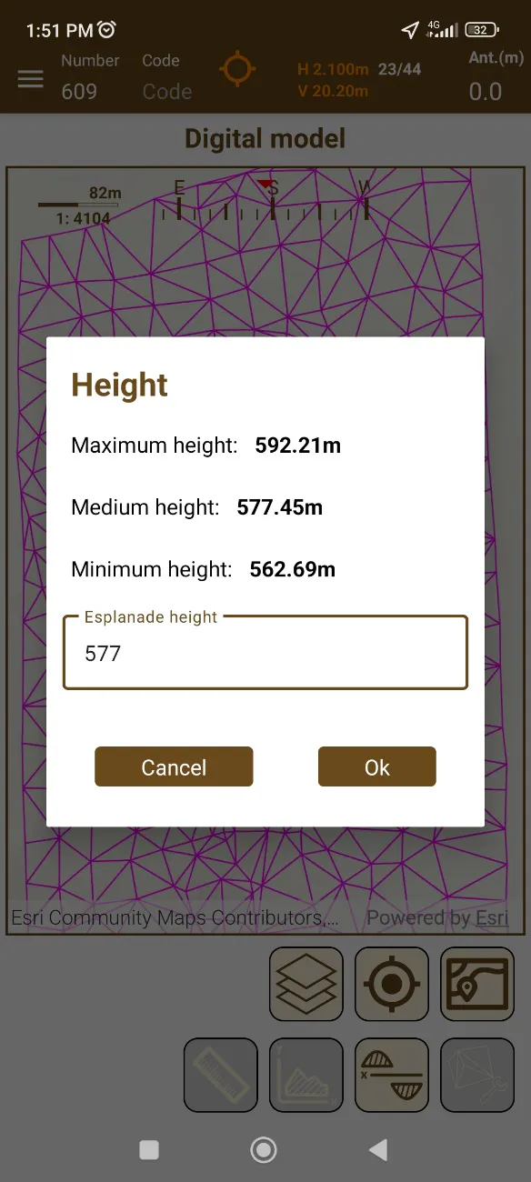
After selecting the polygon, the program will perform some calculations to determine the maximum and minimum dimensions of the model in the selection area and will display them on the screen.
To calculate the volume, it is necessary to write the desired dimension and click accept.
 |
|---|
Figure 119. Area height |
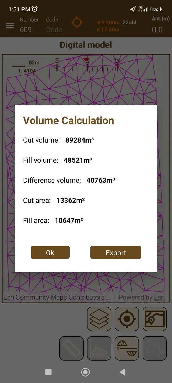
When the calculations are finished, a dialog will be displayed with the resulting values. Keep in mind that this is a completely vertical cut, perpendicular to the esplanade.
The export button allows you to save a file containing these values, with a ".txt" extension on the device, with the possibility of sharing it later.
 |
|---|
Figure 120. Volume calculation result |
Volume Contours

This button calculates the volume between two selected surfaces by generating an intermediate digital model, obtaining the corresponding cut and fill volumes.
Triangulation to create a digital model
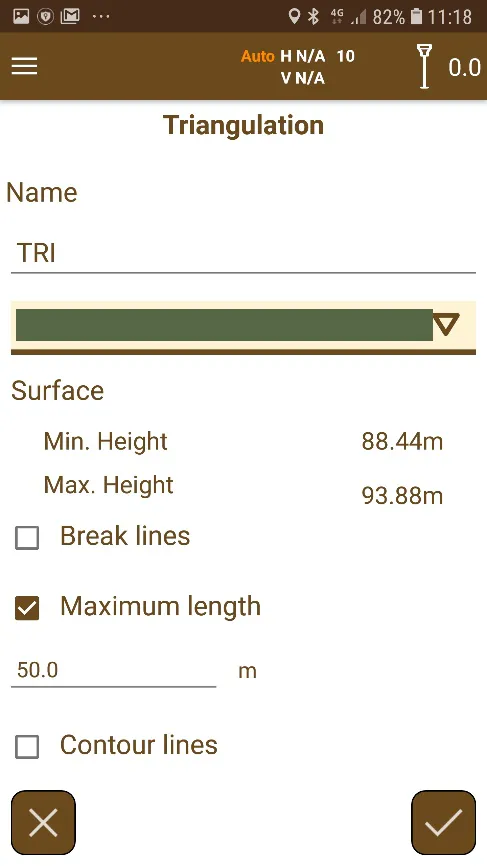
The  button accesses this mode. A digital model is created using a process called triangulation in which the points are turned into triangle vertices, generating an irregular mesh defining the terrain.
 |  |
|---|---|
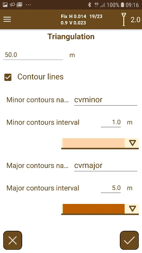
Figure 121. Creation of a digital model (1) | Figure 122. Creation of a digital model (2) |
The following parameters will be required in the screen for configuring the digital model:
Name of the digital model.
Color for drawing the digital model.
Break lines. If this option is enabled and the project contains lines or polylines, a list of them will be displayed for selecting those you want to use as break lines. These lines, either by the characteristics of the terrain or by the peculiar way of seeing it, will be obligatory lines (in advance) in the formation of the digital terrain model. It is not mandatory to define them, but it is highly advisable for the work to have validity and precision, since through these lines the relief is defined by following the existing slope changes.
Maximum distance. It defines the maximum length for the edges of the triangles. If a triangle has an edge with a higher length than this value, it will not be created.
Contour lines. By enabling this option, contour lines can be generated from the generated digital model. There are two types of contour lines:
Minor contours.
Major contours.
Each type of contour is defined by its name, color and height interval between each of them.
By clicking on the accept button, the triangulation process will start. When it is finished, one or several layers will be added to the project:
Digital model layer. This layer manages the visualization of the digital model, and it can be used in surface analysis.
Contour lines layer. If the contour lines option was selected, two layers will be added, with the names typed, that manage each type of contour lines.
It's possible to generate as many models as desired, but if the names of the models or the contour lines match with any other present in the project, it will be replaced by the new one.