tcpMDT Photovoltaic
Configuration - PV25
10.2 Configuration
Through the Configuration option , you can access the menu where you can configure the parameters that affect most of the commands of the Photovoltaic module. Although its values are designed so that it is not necessary to modify them in most cases, it is possible to do so to adapt the application to the user\'s habits and needs.
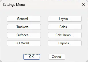
General
It presents the basic parameters for the configuration of the module.
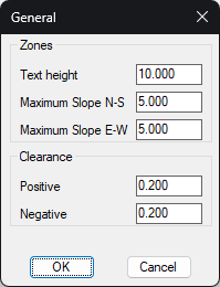
Zones. Text height(m): The height of the texts that define the name of the zone.
Maximum slope N-S (%): Longitudinal (North-South) slope of the new areas to be defined.
Maximum slope E-W (%): Default transverse (East-West) slope of the new zones to be defined.
Clearance. Positive (m): Value of the positive clearance.
Clearance. Negative (m): The value of the negative clearance. It is entered as a positive value.
Layers
Configuration of the default names of the different layers used in the module, as well as the color associated with each of them.
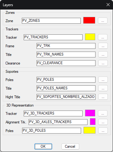
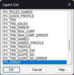
The name of the layer can be entered directly in the dialog or by pressing the "..." which will show us the following window from which we can select the layer from the existing ones in the drawing.
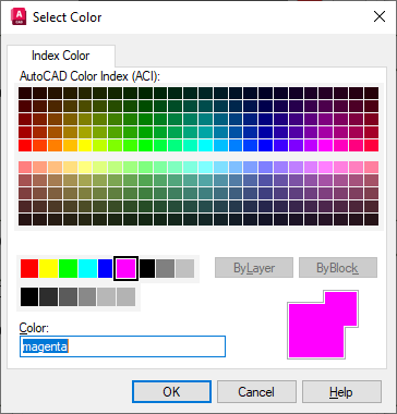
Likewise, by pressing on the color, A color palette will be displayed from which we can select the default color of the layer.
Trackers
In this section, you will configure the related parameters with the trackers.
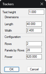
Text height (m): Text height of tracker names.
Length (m): Default length when defining a new tracker type.
Width (m): Default width when defining a new tracker type.
Rows: Number of rows of panels in the default definition of trackers.
Panels per Row: The number of solar panels contained in each of the rows.
Power: Power of each of the solar panels.
Poles
We configure the parameters related to the poles of the trackers.
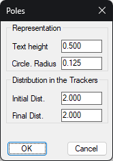
Text height (m): Height of texts related to poles.
Circle. Radius (m): Each pole is graphically represented by a circle. It corresponds to the radius of the circle.
Initial Dist (m): In the definition of the poles, the distance from the first pole to the initial edge of the tracker.
Final Dist. (m): In the definition of the poles of the trackers, the distance from the last pole to the final edge of the tracker.
**
Surfaces
We configure the parameters that affect the creation of the design surface.
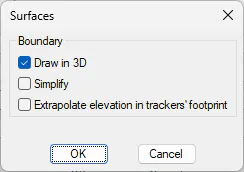
Draw in 3D: We set whether the surface in the CAD is drawn in 2D or 3D at the rendering level. This situation does not affect the final calculation, internally the software always works in 3D.
Simplify: Eliminates redundant vertices on the final surface. This makes it easy to later edit the design surface created with the tcpMDT tools.
Extrapolate elevation inf trachers'footprint: This option only affects the trackers that are in the contour of the area. When creating the design surface, it ends at the outer line of the tracker, to create these triangles with this outer line of the tracker, there are two methodologies.
If the option is disabled, the level of the theoretical grade of the tracker will be repeated on the outer contour of the tracker.
If the option is enabled, the dimension will be interpolated so that the slope is continuous with respect to the previous vertices.
Calculation
Settings related to the "Label Slopes and Elevation Difference" command and the default parameters used by this tool.
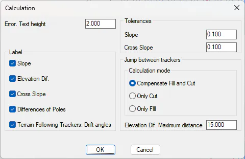
Error. Text Height (m): The height of text associated with the texts that are labeled and that are considered an error due to the constraints associated with the zone.
Label: Default selection of the texts to be labeled.
-
Slope (%): Longitudinal slope of each of the trackers.
-
Elevation Dif. (m): The difference in elevation between trackers.
-
Cross Slope (%): Cross-slope between trackers.
-
Difference of Poles (m): The difference in elevation of each pole with respect to the current surface.
-
Terrain Following Tracher. Drift angle (degrees): Only for articulated. Representation of the angles of the different joints
Tolerances: Longitudinal and transverse tolerances are specified for automatic conversion from drawing. These parameters are used in the Followers option > Convert Followers.
Jump between Followers: For the "Optimize Jump between Followers" tool, the criterion is established by which the vertical jump between consecutive followers is minimized, either by balancing clearing and embankment, prioritizing that there is only clearing or that there is only embankment.
Difference of Cota. Maximum Distance: The jump between two trackers on the same vertical will be analyzed as long as the distance between them is less than this value.
3D Model
Configuration of the parameters related to the 3D representation of the photovoltaic installation.
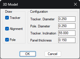
Draw: Selection of the elements to be drawn by default.
Tracker Diameter (m): The diameter of the cylinder that represents the tracker axis.
Pole Diameter (m): The diameter of the cylinder representing each of the tracker poles.
Tracker Inclination (%): Tilt of the solar panel in the 3D representation. Zero is assumed to correspond to a horizontal distribution of the panel.
Panel thickness (m): For a more realistic representation, a thickness is applied to each of the solar panels.
Reports
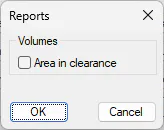
If we activate this option, additionally, the volume report shows the area within the clearance.
Whether or not this option is enabled does not influence the result of the final calculation, but rather the final detail of the report.