
tcpMDT
Segment definition and layer measurement - MDT25
10.3 Segment Definition and Layer Measurement
Once the type section is defined, we will build the road segment. For this, we run the command Roads/Segments> Create/Edit (or Roads> Create> Create/Edit), name the new segment layers.SEG and import its different components. These components can be found in the project folder in the sections file that we have just defined.
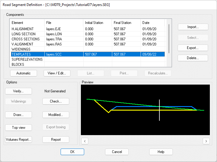
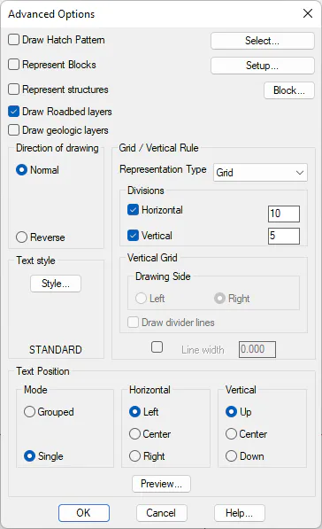
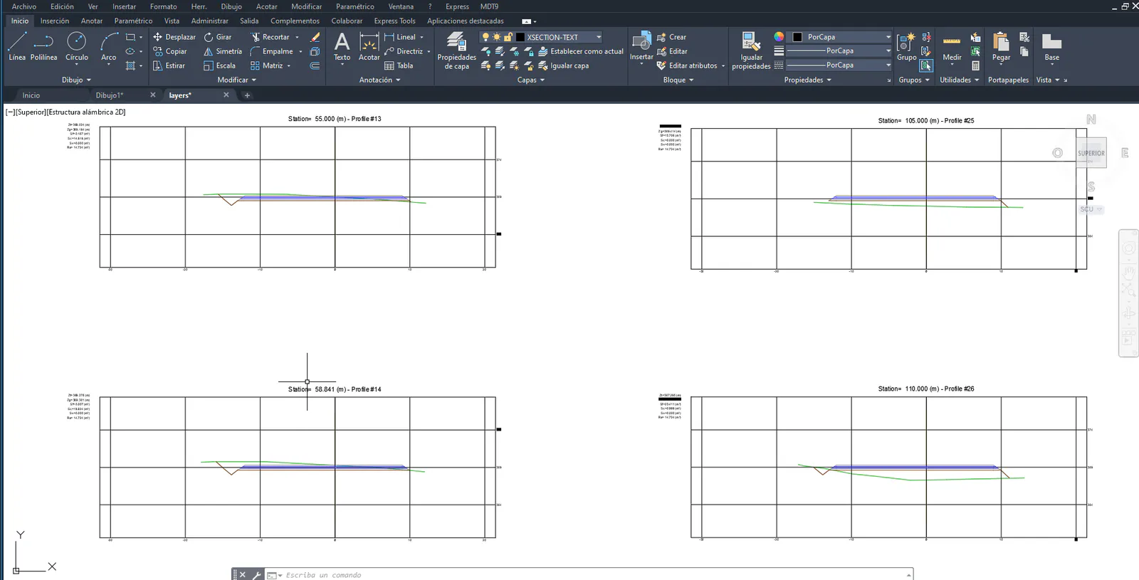
Once we have already built our road or segment, we can draw it. Hence, we run the command Cross-Sections> Draw Cross-Sections (or Cross-Sections> Drawing> Draw) and select the segment that we have just created. In the window that pops up, press the Advanced button and check the Draw Roadbed layers box.
 |
 |
|---|---|
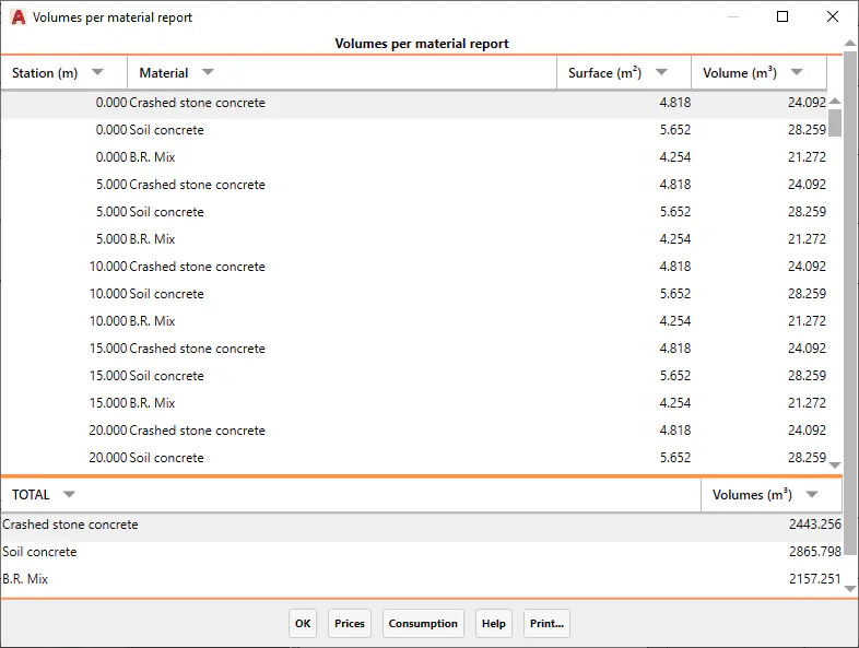
Finally, we are going to calculate the cubic measurement of the roadbed layers. For this, we run the command Quantity Takeoff> Volumes> Roadbed Layer Measurement Report (or Quantity Takeoff> Road> Roadbed > Roadbed Layer Measurement), and validate with the options proposed by default.
File Overview
Once the job is finished, we list the existing project files in the C:\MDT25_Projects\Tutorial07 directory. The main files are the following
File Description
layers.DWG Drawing with the road section
layers.SCC Road sections file
layers.EJE Horizontal alignment file
layers.SEG Road segment file