
tcpGPS
Create a local system with point pairs - GPS v2
8.1 Create a Local System with Point Pairs
this section the user can create, apply or remove a local transformation by adding or modifying control points. Available transformations are 2D/3D Displacement and 2D/3D Helmert. Appendix a transformations - GPS v2 contains detailed information about these transformations.
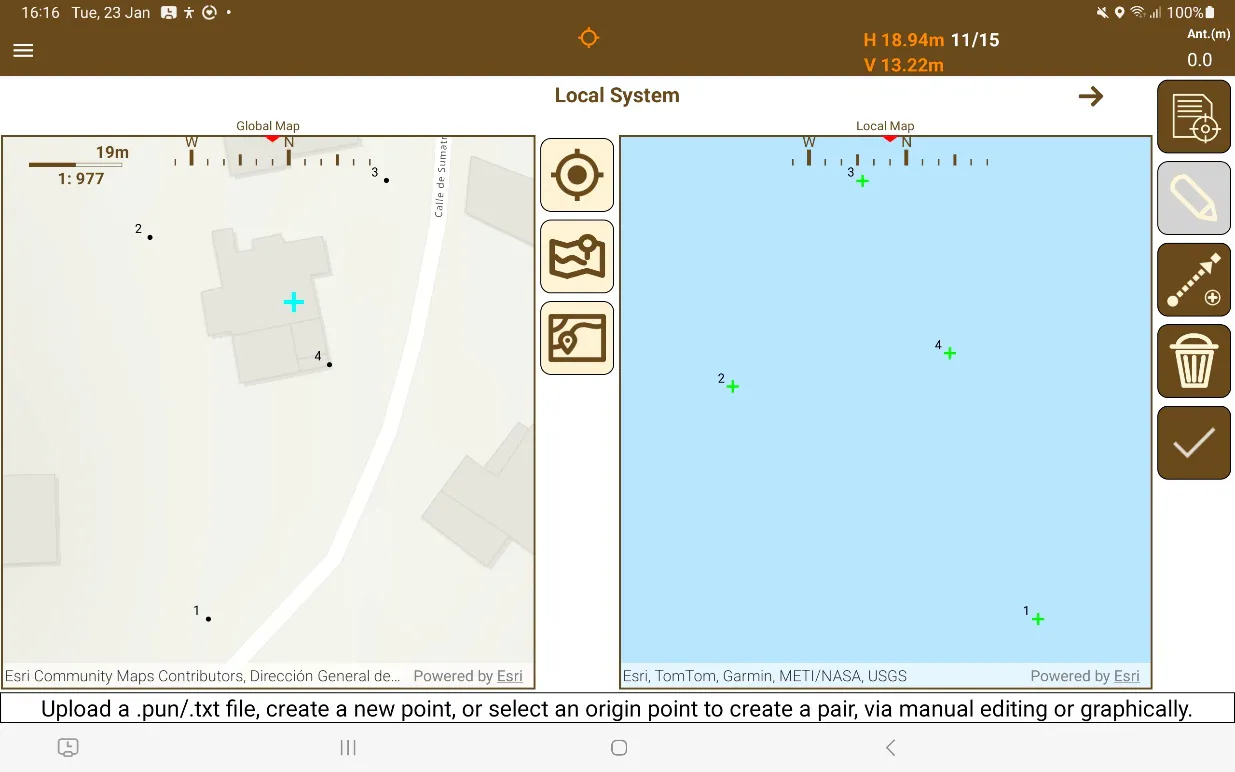
It is recommended to create Local Systems with the device in a Landscape orientation, as it shows both maps at the same time, as shown in Figure 40.
 |
|---|
Figure 40. Creation of a local system with point pairs |
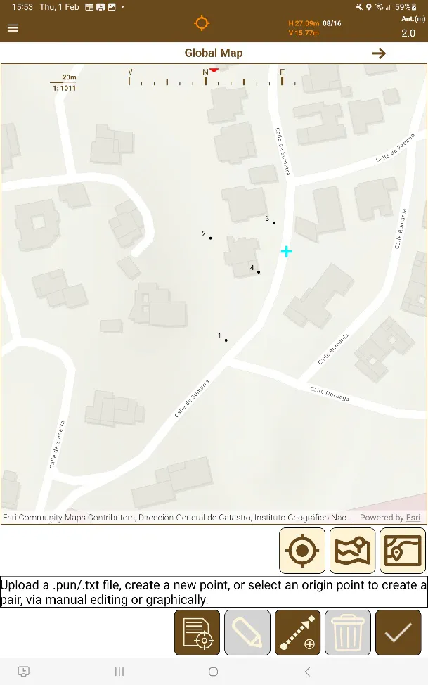
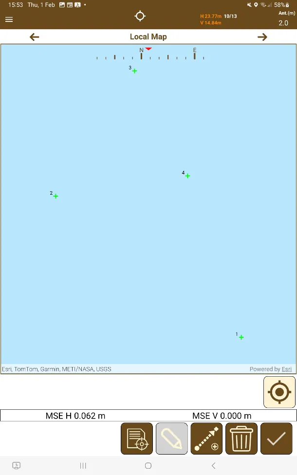
It is also possible to create local systems with the device in the Portrait orientation, and the arrows can be used to swap between the Global Map and the Local Map, as well as the Data View, so maps can be used as if they were side by side.
 |  |
|---|---|
Figure 41. Portrait Global Map | Figure 42. Portrait Local Map |
On the menu of this template are the buttons for the different options that allow the insertion of points and creation of point pairs in addition to being able to select these directly on the map if there are points previously existing in the project database. These are outlined below:
 | Manual insertion of the source and target of the point pair. Allows to create new origin points from GNSS. |
 | Add a target point to a selected source point or edit a selected exsiting point pair. |
 | Import a .txt or .pun file with points that are used as a source for target points. The format is: Number X Y Z Code. |
 | Erases all pairs between source and target points, resetting the transformation, but keeping all the points added. |
After importing a target point file, if the point numbers of the target points match any of the source point numbers, point pairs will be created automatically. This is the reccomended way of creating local systems quickly if there are plans on using it beforehand.
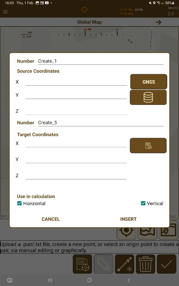
When manually inserting, or editing the target point paired with a source point, a dialogue is displayed to allow the user to edit the information of the points. This dialogue has options for typing the source point coordinates, using the current GNSS receiver position, or selecting points from the database for source coordinates, or the imported file for target coordinates.
 | 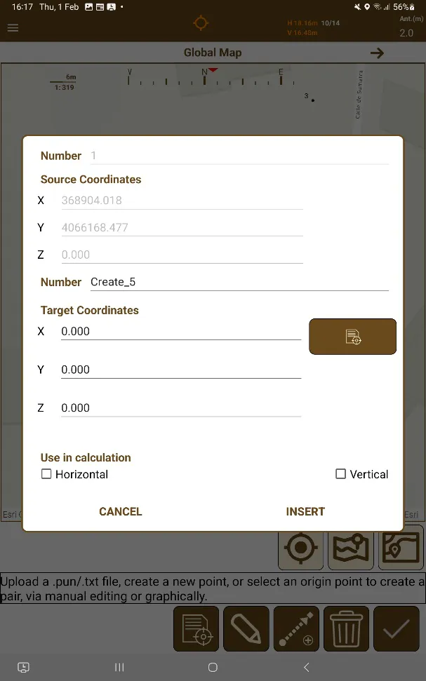 |
|---|---|
Figure 43. Point Pair Creation | Figure 44. Point Pair Editing |
These dialogs have the following icons:
 | Obtains the current geographical location (X,Y,Z) of the current GNSS receiver and adds it to the Source Coordinates. |
 | Obtains the number and Source Coordinates of a point existing in the project database. |
 | Obtains the number and Target Coordinates of a point existing in the already uploaded target points file. |
It is important to remember that each point can only be in a single pair. To avoid duplicate pairs, the application automatically removes points already existing in pairs from the list of points that can be selected from both the source  and destination
 point lists, as well as not letting you save the pair if either the source or target points already exist in a pair.
To keep data integrity intact, if the point number written in the source or target point textboxes is the point number of a point that already exists in either list, the coordinate textboxes will change to the X Y Z data of the point that has that point number, and it will not be able to be changed. This way the integrity of the pre-existing numbers is kept.
Once point pairs are created, the numeric screen shows detailed information about the transformation, the points used, leftovers and errors.
Using the dropdown different types of lists can be selected:
Source points list: The coordinates of these points will be used as origin coordinates.
Target points list: The coordinates of these points will be used as target coordinates.
Leftovers list: Show the differences between each origin and target point. This is the list that has all of pairs already defined in the local system.
The number of control points will enable one or several transformations that can be selected in the spinner of the numeric screen.
Each transformation will be characterized by a set of parameters:
MSE 3D: Medium Square Error in 3D.
MSE H/V: Medium Square Error in horizontal and vertical.
Max. Res. X/Y/Z: Maximum residue in X/Y/Z coordinates.
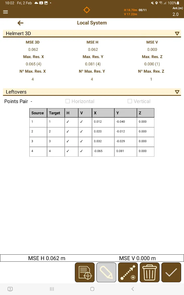 |
|---|
Figure 45. Transformation data |
After selecting a point pair in the list, it is possible to toggle the horizontal or vertical transformation of each pair with the checkboxes that become enabled when you choose a source/target point that is part of a point pair, or an element from the leftovers list.
The transformation can be saved to the project by pressing the icon  . A name for the file will be requested and the transformation will be stored in a file with the .ntr extension into the project folder.
The application will ask whether to only transform points with raw data or transform all points. Points with raw data are the ones that have been manually taken in the survey screen. Points without raw data are the ones that have been imported.