
tcpMDT Photovoltaic
Create design surface - PV25
5.3 Create Design Surface
Once the trackers for one or more zones have been designed, this option allows you to create a theoretical surface for each zone in the project. The command has two modes of operation: selecting a zone in the drawing, or using the command line option Multiple or All.
If you select a single zone, a window appears that allows you to select the name of the surface to be created.
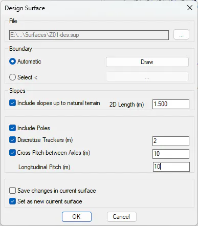
By default, the program will automatically create an outline around the trackers in the area. In case this outline does not meet our expectations, we can use the Draw button to represent this outline in the drawing. Then, by canceling the command, and manually modifying the outline, you can recreate the design surface with the option to Select the modified boundary.
Including slopes up to the natural terrain enables the possibility of specifying a slope in the trackers that are located in the contour. A distance in meters is entered that specifies the distance to the cut from the natural terrain
Include Poles allows a vertex to be created on the surface for each of the tracker poles. If this option is not enabled, only the vertices corresponding to the start and end of the tracker are included.
With the Discretize Trackers option, you can specify a discretization distance (every 2m, for example) so that vertices will be created along the longitudinal development of the tracker. These vertices will be interpolated every two successive poles, or between the start and end vertex of the tracker, depending on whether the previous option is used.
If trackers are far apart from each other, it could happen that the resulting triangulation is not a continuous surface, and each of the trackers is triangulated separately. In these cases, by activating the Cross Pitch between Axles, the transverse and longitudinal distances separating our trackers can be entered. In this way, program will try to create a continuous surface between the trackers, and surface discontinuities may appear when the distances between the trackers exceed the values entered.
Optionally, you can also set the created surface as the current MDT surface. If a current surface already exists in MDT, you can save the changes to the surface that have yet to be saved by activating the corresponding option before switching to the new current surface.
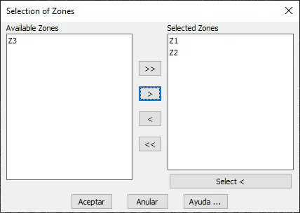
If you select the Multiple option, a window will appear where you can select the zones you want to work on. You have to include in the list on the right the zones on which you want to act.
Next, we can decide whether we want to reuse the same parameters previously used in each of the selected zones (option Specific to each zone) or want to use common parameters to all zones. In the latter case, you can also save those parameters as the default option in all zones.
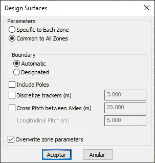 .
Finally, a message will appear on the command line for each surface file created, indicating the number of triangles that the surface contains.