
tcpMDT
Lines - MDT25
7.3 Lines
In addition to the Calculate command, MDT includes commands from this previous version. These commands can be used to edit an element or an alignment, but it must be borne in mind that upon doing so, the information about the alignment type (Fixed, Mobile etc.) is eliminated.
Layout Elements
Layout elements are elementary geometric principles with which more complex alignments are formed. The program distinguishes between three types of layout elements: straight lines, circular curves and clothoids.
The layout elements are defined by a point of origin, an initial azimuth and a length calculated by the system.
Straight lines
The straight line is defined by its initial (I) and final (F) points. The initial azimuth and the length are calculated automatically and they are indicated in the dialogue which is shown by pressing the Details button in the command Edit
.
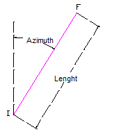
The straight lines are drawn as line type entities or as a polyline with two vertices.
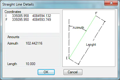
Any kind of modification can be made to these elements using the CAD commands: copy, rotate, move, lengthen, shorten etc.
Circular Curves
The curve type layout elements are defined by their center, initial and final angles and their radius. The latter will bear a positive sign if it moves forward in a clockwise direction or negative otherwise.
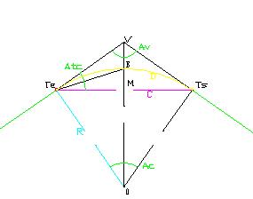
The coordinates sow in the Details dialogue of the command Edit
are:
Te. Input tangent of the curve.
Ts. Output tangent of the curve.
O. Centre.
V. Vertex.
B. Bisector. Arc midpoint.
M. Chord midpoint.
On the other hand, the magnitudes indicated are as follows:
R. Radius.
T. Tangent
VB. Distance to the vertex: VB.
D. Development.
C. Curve length.
Sc. Semi-chord.
Fl. Arrow
Ac. Angle in the center: TeOTs
Av. Angle at the vertex: TeVTs
Atc. Angle between tangent and chord: VTeTs
The circular curves are drawn as arc type entities or polylines with two vertices and curvature.
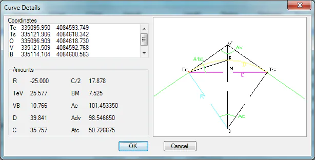
As with the straight lines, any kind of modification can be made to these elements using the CAD commands: copy, rotate, move, lengthen, shorten etc.
Clothoids
The clothoid type layout elements are defined not just by their origin and initial azimuth, but also by their input and output radio and their parameter. Provided that the following is complied with:

where L is the length of the clothoid, A is the parameter and R is the radius. The clothoids may be defined between a straight line and a curve (Re=
y Rs=R), between a curve and a straight line (Re=R y Rs=
The coordinates sow in the Details dialogue of the command Edit
are:
O. Link circle center.
Te. Input tangent of the curve.
Ts. Output tangent of the curve.
PI. Tangent intersection point.
On the other hand, the magnitudes indicated are as follows:
X. X-alignment of the final point.
Y. Final point ordinate.
X0. X-alignment of the center.
Y0. Ordinate of the center.
Tc. Short tangent.
Tl. Long tangent.
Tau. Angle formed by the two tangents at the vertex.
IncR. Offset.
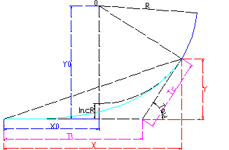
For the clothoids a discretization is drawn of the theoretical curve by means of a polyline. The drawing interval may be specified on the configuration. This parameter only affects the representation as the results are always calculated analytically.
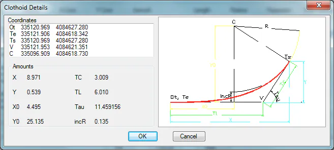
The polyline representing a clothoid can be copied, revolved and moved using the CAD commands. The modifications to individual vertices are not considered. To modify the length of a clothoid the command Edit Clothoid
must be used.
Elements
Once a set of layout elements has been drawn, they can be grouped with a view ensuring that a modification to any one of them modifies certain parameters of the adjoining elements in such a way that the alignment they form maintains its coherence. These modifications must be carried out with the commands provided by the program. If they are carried out with CAD commands, the risk is run of breaking up the grouping or failing to comply with the azimuth continuity conditions imposed by an alignment.
Through the elements library we can create sequences of connected layout elements which can be inserted as part of a more complex alignment.
Alignments
Although the elements contain all the information required to analytically define the layout, the element needs to be converted into an alignment in order to be able to use it in profile calculation and setting out operations using the command Convert Alignment.