
tcpMDT
Introduction - MDT25
12.1 Introduction
MDT allows one to create an alignment's cross-sections using a series of components or elements that, along with the customized superelevation table and the assignment of materials for different roadbed layers, determine the cross-section template in. These components include:
-
Platforms
-
Ditches
-
Median elements
-
Cut slopes
-
Fill slopes
-
Roadbeds
-
Safeguard ditches
-
Wall and structures
By assigning these sections to an alignment's different sections and margins, one can generate the terrain's construction cross-sections. One can subsequently proceed to check, list, draw, calculate volumes, etc.
A file with the .SCC extension that stores all the information needed to configure the project's roads is generated throughout this process.
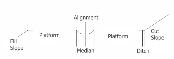
MDT distinguishes two types of templates for the platform type assigned:
-
Urban templates.
-
Road templates.
The main difference between them is that in the road templates it is possible to define the central reservation (median) elements and two types of roadbeds also exist, one for the left roadway and another for the right.
It is possible to work with the template file or with the segment, in the latter case the segment must already be comprised of all the road elements including the template type.
Definition of Platform Vectors 
This option is located under Utilities > Settings > Cross-Sections and the purpose of this option is to define the default codes and dimensions of the different vectors that can constitute the platform. Each one of these has a numeric Code, a Name, relative X and Y displacements, and a value to indicate whether it can be superelevated or not.
The codes must increase from the horizontal alignment (value 0) up to the ends of the profile, both for the left and the right. The buttons Change, Insert and Delete can be used to modify the configuration, which will be saved in the file Secciones\VecPlat.dat in the directory Config.
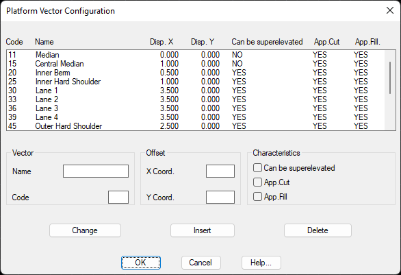
Additionally, three properties have been added to each one of the vectors:
App. Cut: If this is checked the vector will be applied to the platform in the case that the vector\'s point of application is cutting.
App. Fill: If this is checked the vector will be applied to the platform in the case that the vector\'s point of application is in fill.
Texture: Texture to apply to the vector in question for later 3D visualization of the road with the commands in Maps/Realism menu.