tcpMDT
Creating cross sections - MDT25
3.1 Creating Cross-Sections
In this exercise, we are going to show two different methods to calculate the volume between the original terrain and the proposed terrain: by difference of cross-sections and by difference of meshes.
Hence, we will first open the surveyInitial.dwg file that can be found in folder C:\MDT25_Projects\Tutorial03.
Then, we import the alignment that we will use to generate the profiles. In this case, we will import the Alignment1.eje file that we can locate in the cited folder. For this, we execute the command Horizontal Alignments> Import Alignment (or Horizontal Alignments> Drawing> Import).
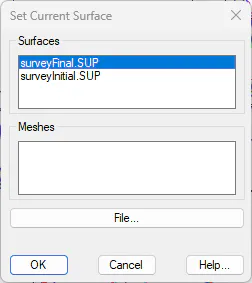
Once the axis is imported, we are going to set the surface from which we will generate the first group of profiles as current, for this, we run the option of Surfaces > Set Current Surface, then the following window will be shown with the existing surfaces in the work folder.
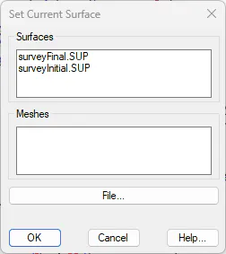
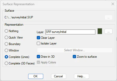
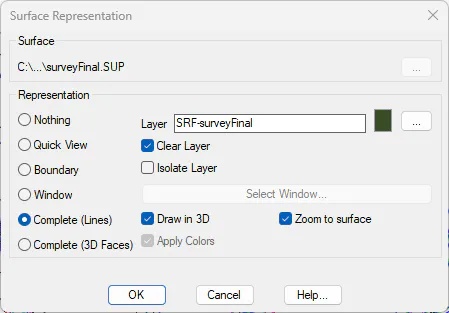
Select surveyInitial.SUP and press the OK button. The following window will be displayed where we indicate how to represent the surface, select the options that can be seen in the following screenshot.
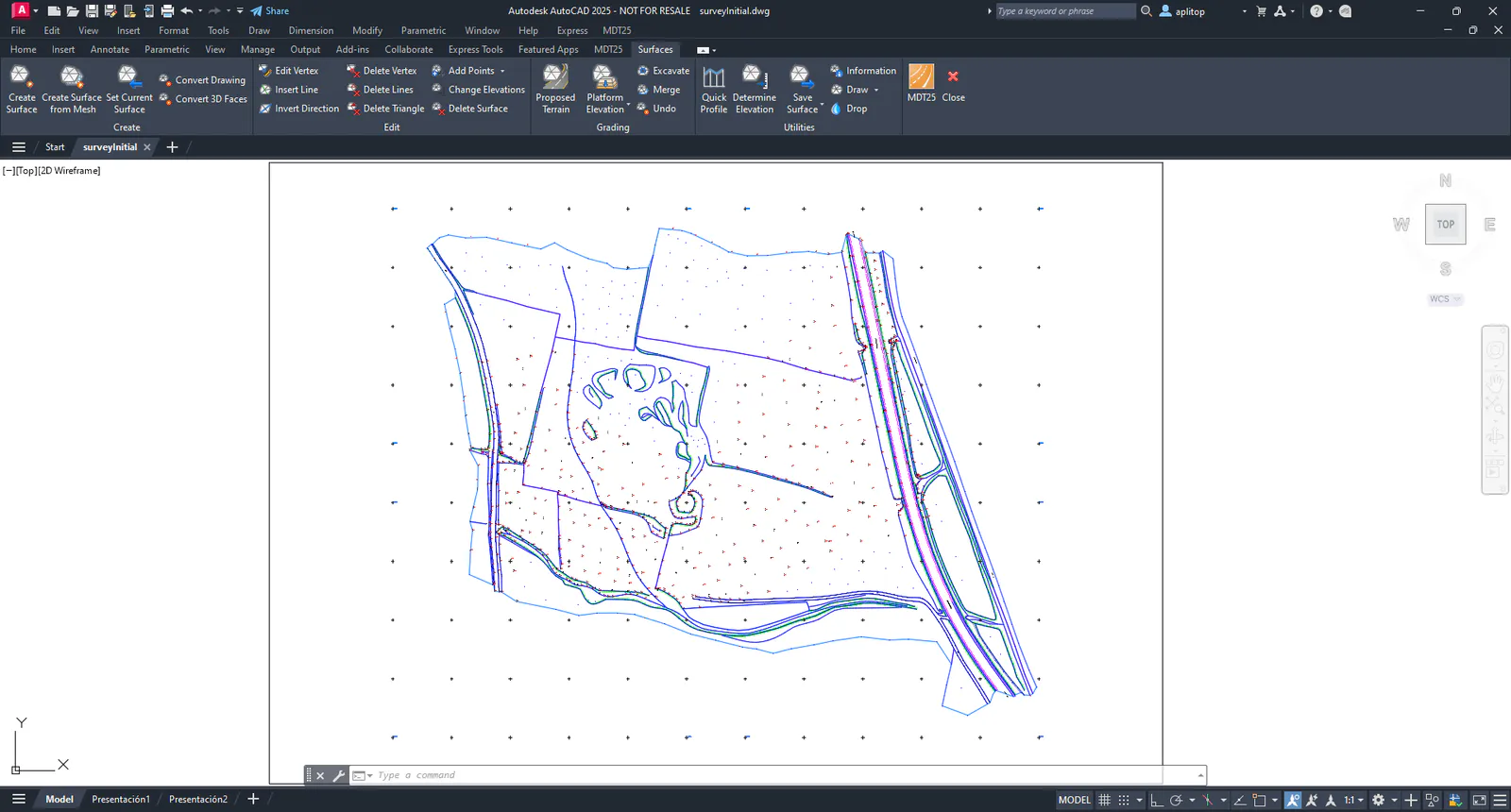
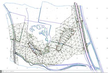
El dibujo actual se mostrará con la superficie seleccionada:
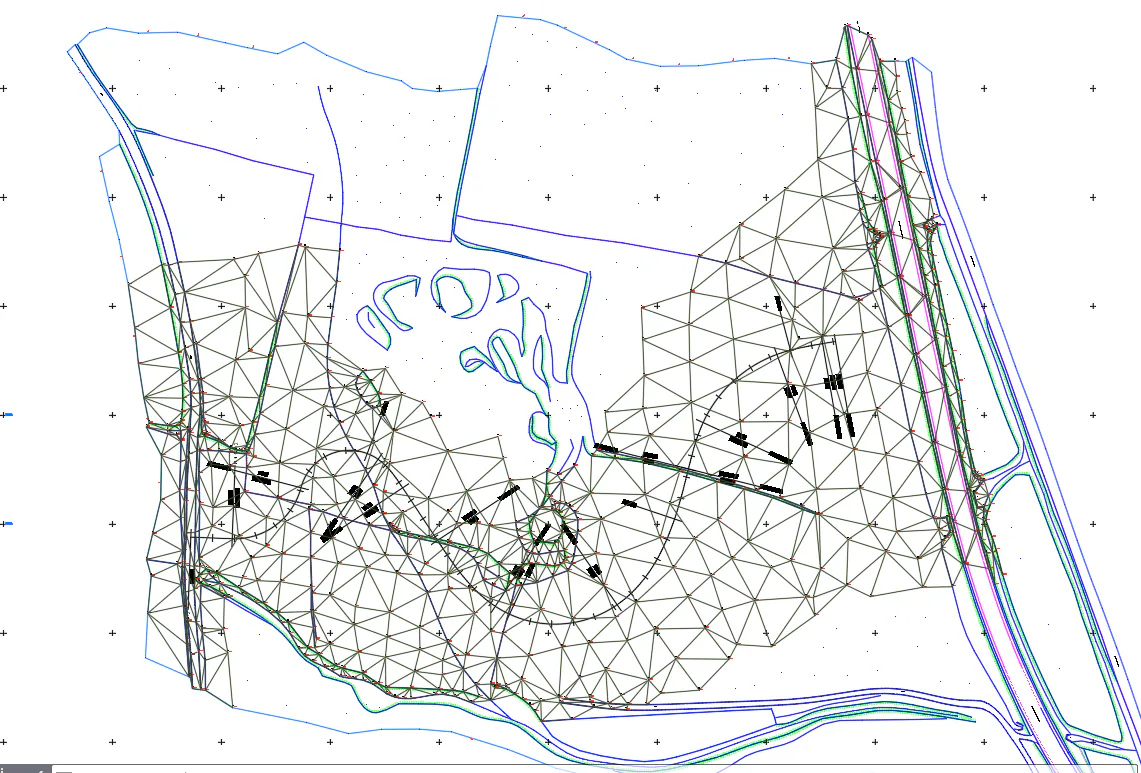
Next, we will obtain cross sections thereof with the command Cross-Sections> Create Cross-Sections (or Cross-Sections> Create> Create Cross-Sections) from the contour lines. Select the alignment graphically and press the Source button. Choose Digital Terrain Model.
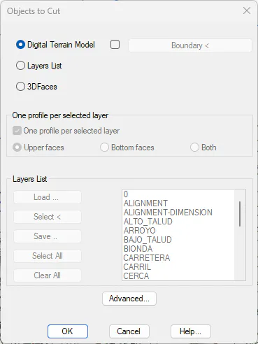
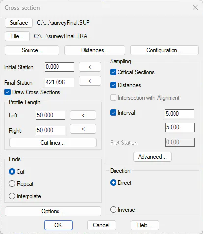
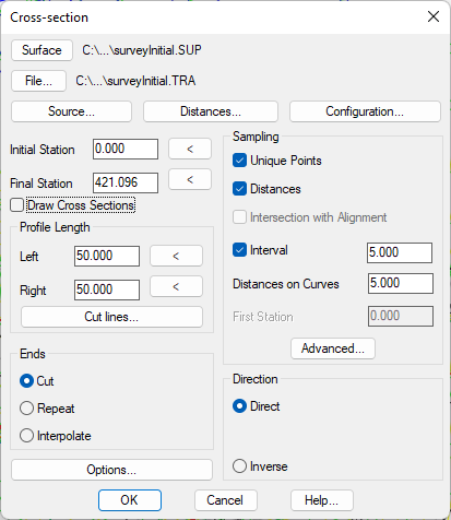
Press OK and specify the parameters shown in the following dialog box. Press the File button and name as surveyInitial.TRA and press OK again.
Now we are going to generate the second group of profiles with the same axis, for this, we open the drawing SurveyFinal.dwg and set the SurveyFinal.sup surface file as current.
Then we generate the crossbars from this new surface, for this, we proceed in the same way as with the previous surface, only now we will call the crossbars file SurveyFinal.tra. We use the same axis, which we can designate in the drawing.