
tcpTunnel Scan
Tunnel templates - TSCAN1
4.7 Tunnel Templates
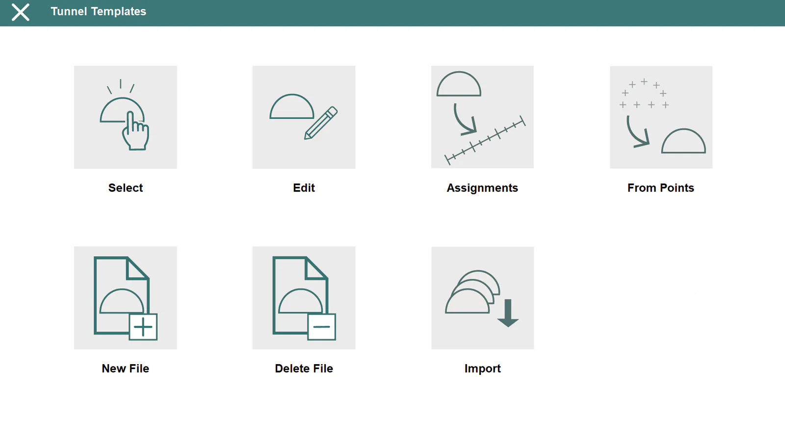
These files have *.TNL extension and are compatible with TcpTunnel CAD.
The application allows one to work with 3 kinds of cross-sections:
Simple template: A circular template defined from a radius.
Compound template: Defined from a radius and sidewalls.
Complex template: Defined by a succession of curved and straight sections.
Of these, only the first two can be defined in the field data recorder itself. Complex cross-sections have to be created in TcpTunnel CAD or TcpScancyr program. All cross-sections created in this module will be treated by the application as if they were complex, even if they are simple or composite cross-sections.
Said cross-sections can be included or not in the road surface or inverted arch zones. They will be considered as Open if they do not include them and Closed otherwise. The kind of cross-section one wishes to create has to be indicated in the field data recorder, while in CAD it is done automatically depending on whether the polyline created is open or closed.
The cross-section center and three distances marking where the alignment is marked on the ground plan, the vertical alignment and the superelevations will be requested in all cases. One must additionally specify how the cross-section varies as a function of the superelevations (see Edit section).
The vertical alignment and superelevation application point should be within the tunnel cross-section.
All the data referring to cross-sections requested and shown in the application are understood to be in the forward direction of stations on the project's alignment.
The survey and set out profiles, set out front and position options allow one to divide the section into specific theoretical points starting off from the keystone up to the values indicated to the left and the right of the keystone. Exclusion zones can be defined. See Features and Functionality > Theoretical Points of the Tunnel Template.
Select
Allows one to select a tunnel template file in the current project.
Edit
Allows one to view and delete templates of all the types supported, in addition to editing and creating simple and composite cross-sections.
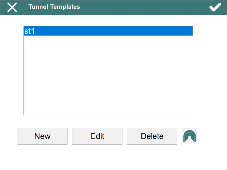
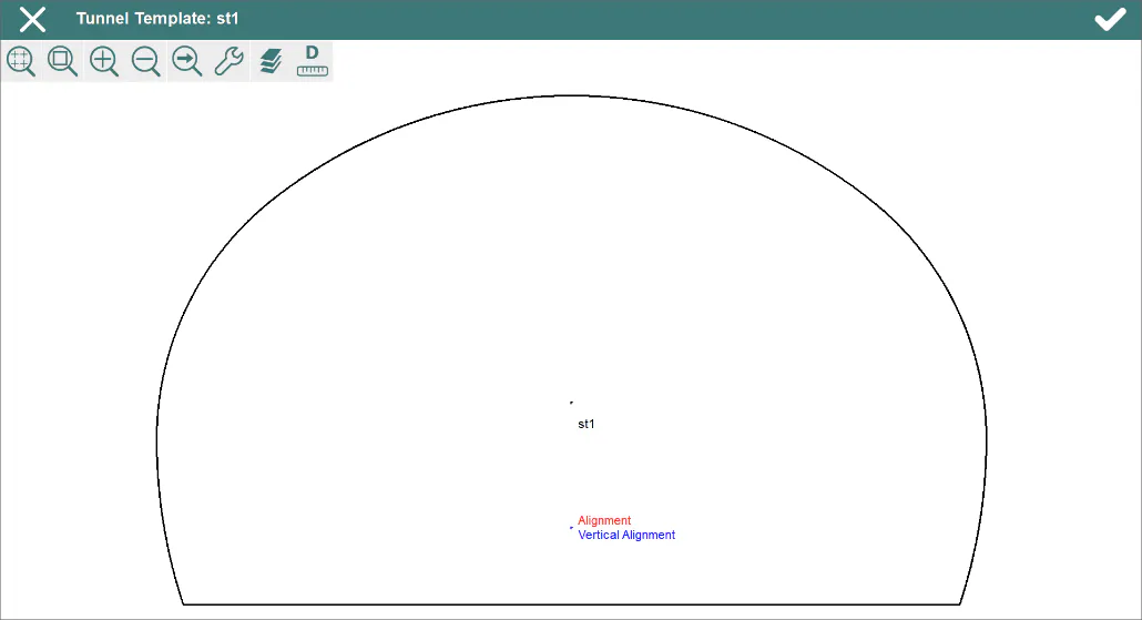
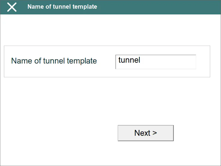
A wizard to edit and create templates is shown. It provides detailed information on all the parameters that define tunnel's template.
Name of the tunnel template:
Type of tunnel template:
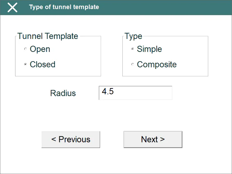
Only the Radius value should be entered for simple cross-sections, while Radius and Sidewall length should be entered for composite cross-sections. In the latter case, the cross-section will be created with straight sidewalls that start at the left-hand and right-hand points of the semi-circle having the radius indicated.
Both types of cross-sections can be created Closed or Open. In the latter, the right and left-hand limits are marked by the vertical alignment and superelevation application point.
Application Points:
The tunnel cross-section center's coordinates should be entered in this section, as should the series of distances described below. It should be taken into account that the intersection point between the vertical straight line passing through the center thus defined and the tunnel cross-section will be considered as the keystone.
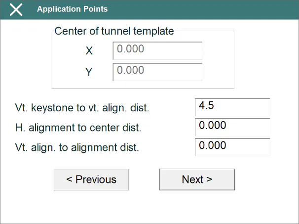
Vertical keystone to vertical alignment distance: A positive value should be indicated if the keystone point is above the vertical alignment and superelevation application point and negative otherwise. Under normal conditions, this value should always be positive. The vertical alignment and superelevation application point should be within the tunnel template.
Horizontal alignment to center distance: A positive value indicates that the horizontal alignment is to the right of the cross-section's center and a negative value indicates it is to the left. Differently to the vertical alignment and superelevation application point, the horizontal alignment's application point can be defined to be outside the tunnel template.
Vertical alignment to alignment distance: In this case the reference is the horizontal alignment's application point. One will therefore have to indicate a positive value if the vertical alignment and superelevation application point is to the right of the alignment and a negative value if it is to the left.
Advanced (Superelevations):
In the last section of the wizard, one should indicate how the template behaves depending on the project's superelevations.
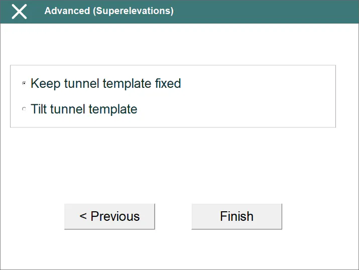
Keep tunnel template fixed: The tunnel template doesn't rotate with superelevations.
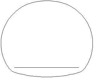
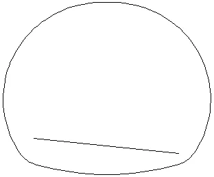
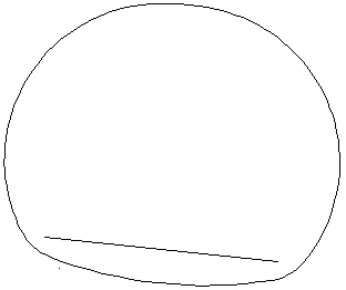
Tilt tunnel template: Taking the pivot point to be the point where the vertical alignment and superelevations are applied, the cross-section will tilt according to the superelevation of the station in question. This superelevation is calculated by averaging the superelevations on the left and right.
Tunnel Template Assignment
Allows one to indicate which templates will be used along the length of the project's horizontal alignment.
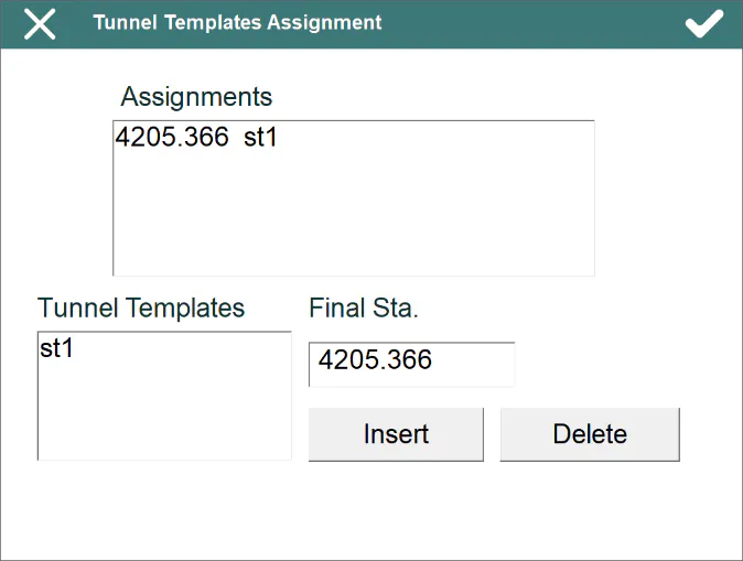
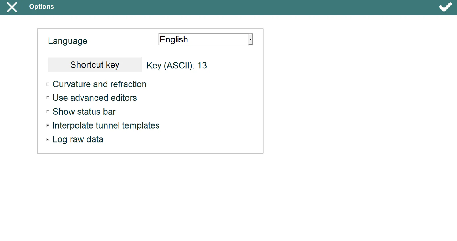
Should various templates be assigned, the program will interpolate between them, if it is well established in Settings > Options.
The names of all the templates in the current file appear on the Tunnel Templates list.
The last station of the current project's alignment initially appears in the Final Station box.
In order to create an assignment, you should select the template name in the Templates list, indicate the final station up to where the template will be used and click on the Insert button. In the example shown on screen, 2 is used from the initial station of the alignment up to station 10.000.
In order to delete an assignment, you must select it from Assignments list and click on the Delete button.
Create from Points
Allows one to create an Open or Closed template from the points taken within the range of stations initially defined by Initial Station and Station Tolerance.
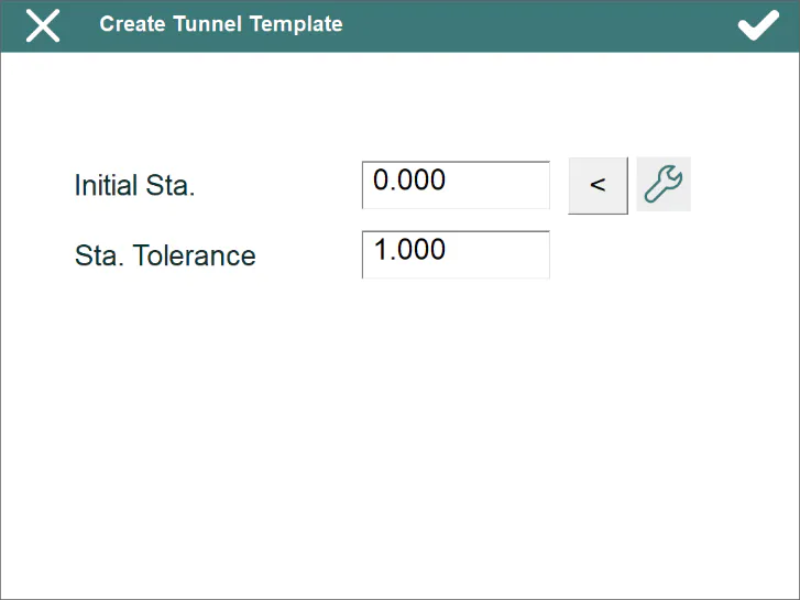
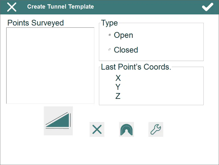
The X, Y and Z coordinates are shown for each point observed.
The numbers of the measured points are shown in the Points list.
The tunnel template being created can be viewed at all time pressing  button, and any point not desired can be deleted pressing
 button.
New File
Creates an empty tunnel templates file.
Delete File
Deletes a tunnel templates file from the disk. If the file selected belongs to the active project, the link to the project is also deleted.
Import
This option allows one to import tunnel template files, with TRA extension, created with TcpScancyr, a single tunnel template included in a DXF file or tunnel templates included in a LandXML file.
The DXF file must contain only two CAD entities, a POINT entity, defining the position of the horizontal and vertical alignment, and a POLYLINE, LWPOLYLINE or CIRCLE entity, defining the tunnel template.
When tunnel templates are imported from a LandXML file, the layers must contain only one tunnel template and this tunnel template cannot be defined in different parts.
On both cases, the program will create a new file with TNL extension and it will include it in the project, replacing the current one. On the other hand, the existing assignments will be removed and the new ones will be added. When TcpScancyr file is selected, the assignments are calculated from the stations contained in the TRA file and, in case of DXF file, only one assignment, along the horizontal alignment, is added.