
Support
CAD Insertion of Georeferenced Images
Objective
The purpose of this document is to tell users the steps necessary to download, install and execute the INSIMG command, which allows you to insert raster images (JPG, PNG, TIF) in real coordinates using their associated georeference file (.JGW, .JPGW, .JPW, .PGW, .TFW, .WLD).
This is useful, for example, to insert the floor plan images generated by Tcp PointCloud Editor at their actual scale and position.
1. Downloading the LISP file
The command is distributed as a file named insimg.lsp.
Download the file from here and save it to a folder, for example C:\Tcp PointCloud Editor Projects.
2. Installing the command in the CAD
To load the command into the CAD:
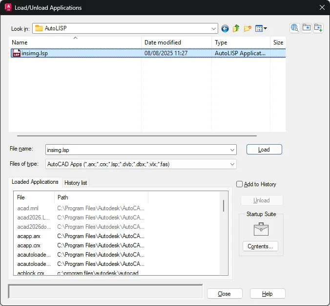
Run the APPLOAD command on the command line.
In the dialog box, navigate to the folder where the file was saved.
Select it and press the Load button.
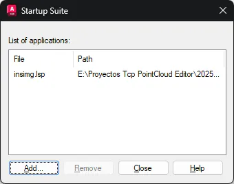
If you want the command to always be available when you start the CAD, add it to the Startup Suite from the same dialog box.
3. File requirements
For the command to work correctly, you need:
Image file in JPG, PNG or TIF formats.
Georeference file with the same base name and one of the following extensions:
JPG: .jgw, .jpgw, .jpw
PNG: .pgw, .pngw
TIF: .tfw, .tifw
Any format: .wld
Both files must be in the same folder.
Example:
Plane_31.000.jpg Plane_31.000.jpgw
4. Running the command
On the command line, type: INSIMG
Select the image file.
The command will automatically search for the associated georeference file. If it does not find it, it will let you select it manually.
The command will read the resolution and rotation from the georeference file, as well as the actual dimensions of the image in pixels.
It will insert the image at its actual coordinates and at the correct scale.
When finished, it will automatically zoom to frame the entire image in the view.