
tcp PointCloud Editor
Raster editor - PCE
14.2 Raster Editor
Description
The Raster Editor is shown after launching the Raster Editor command.
With this tool, you can draw entities on images generated from point clouds.
Details
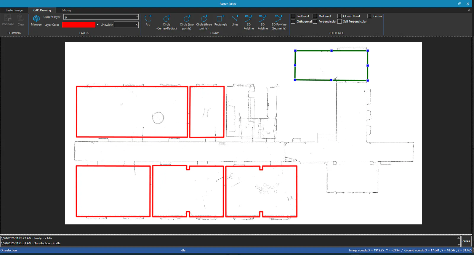
This editor is like a secondary application that has a ribbon menu, a drawing area, and a status bar.
Ribbon Menu
Raster Image Tab
RASTER IMAGE Group
Front Band Width and Rear Band Width allow you to set the band of points to rasterize.
Pixel Size allows you to set the pixel size in the image, while Density Range allows you to define the vertical point density range that will be represented in the image.
Use the Update command to update the image, which will be regenerated using the previous parameters.
Using the Export command you can export the generated raster image.
CAD Drawing Tab
DRAWING Group
The Vectorize command displays the vectorization parameters dialog for automatic detection of straight segments, which will be included as 3D polylines in the current layer.
The Clear command will delete all drawn entities.
LAYERS Group
Use the Manage command to open the Layer Management dialog, where you can add and remove layers, as well as change their properties.
With the Current Layer dropdown, you can select the active layer on which new entities will be drawn. Layer Color and Line Thickness change those properties of the current layer.
DRAW Group
In this group you will find the commands to draw new entities, which can be: * Arc to draw an arc using three points. * Circle (Center-Radius) to draw a circle using two points, the first being the center and the second on the perimeter. * Circle (Two Points) to draw a circle using two points, the first being one end of the diameter and the second the other end. * Circle (3 Points) to draw a circle using three points on its perimeter. * Rectangle to draw a rectangle using three points. The first two points define one side of the rectangle and the third point defines the width/height. * Lines to draw multiple lines consecutively. * 2D Polyline to draw a 2D polyline formed by lines and/or arcs. Hold down the Shift key when you want to draw arcs. * 3D Polyline to draw a 3D polyline formed by lines. * 3D Polyline (Segments) to draw a 3D polyline by defining segments. Each line is defined by a segment given two points. Consecutive lines will join each time a new segment is defined.
Vertex designation is done using the left mouse button. You can control entity creation using certain keys: * ESC (Escape) to cancel the command. * Enter to finish the command. * Del (Delete) to remove the last designated point. * C (Close) to close the entity (lines/polylines).
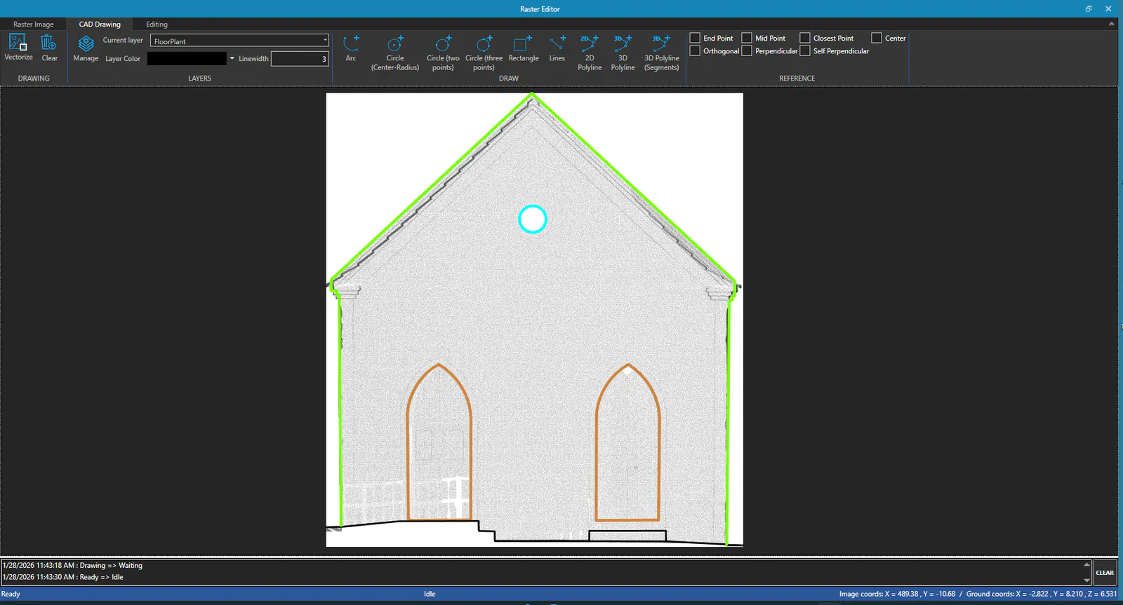
REFERENCE Group
In this group you can set drawing references to help in creating and editing entities. The available references are: * End Point to activate the reference to the end point of entities. * Mid Point to activate the reference to the mid point of entities. * Nearest Point to activate the reference to the nearest point of entities. * Center to activate the reference to the center of entities (Arcs and Circles). * Orthogonal to activate the orthogonal reference to the view (X or Y axes) * Perpendicular to activate the perpendicular reference to entities. * Auto Perpendicular to activate the perpendicular reference to the last drawn line.
Edit Tab
SELECTION Group
Use the Select command to select entities in the drawing area using a rectangle. Use the Clear Selection command to cancel the current entity selection (deselect all).
The Set Layer command allows you to move the selected entities to the specified layer.
Using the Move CAD Entities command you can move the selected entities to a new position, specifying a base point and a destination point. Rotate CAD Entities allows you to rotate the selected entities around a base point, specifying the rotation angle using two points. With the Copy CAD Entities command you can copy the selected entities, similar to how it's done with Move.
The Delete CAD Entities command will delete all currently selected entities.
MODIFY Group
The commands present in this group allow you to: * Extend to extend the end of an entity to its intersection with another entity. * Trim to trim an entity by the touched segment with respect to its intersection with another entity. * Join to join two polylines into one, by the straight segments designated in each of them. * Merge to merge two entities into one, from the extreme vertices of each of them, which must coincide in position. * Split to trim or split an entity, using two points designated on it.
Drawing Area
In the drawing area, an image generated from a point cloud view is displayed.
Using the available commands, the user can draw and edit entities on the raster image.
- Left mouse button to designate points or select entities/hotspots of selected entities.
- Middle mouse button to pan the view.
-
Mouse wheel to zoom in and out.
-
ESC key (Escape) to finish or cancel the current command.
- Enter key to repeat previous command or finish the current command.
When selecting an entity, hotspots will be displayed, which can be used to move vertices, lines, arcs and circles. Hotspots can be dragged with the left mouse button to modify the entity.
Message Area
Located at the bottom of the drawing area, the message area displays information about the operations performed and the current one. You can resize the height of the area by dragging the top bar up or down. Use the CLEAR button to the right of the message list to clear all messages.
Status Bar
In the status bar, the editor status (command or operation in progress) is displayed along with pixel coordinates, terrain coordinates.