
tcpGPS
PRO slope control PRO version [PRO] - GPS v2

14.7 Slope control (PRO version)
Slope control configuration
In the control of slopes, the verification of the state of the terrain is made according to the road. In order to carry out slope control, the road must have a vertical alignment and at least one cross section.
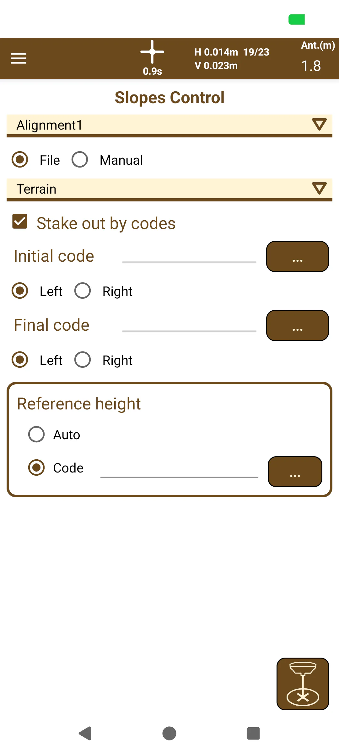 | 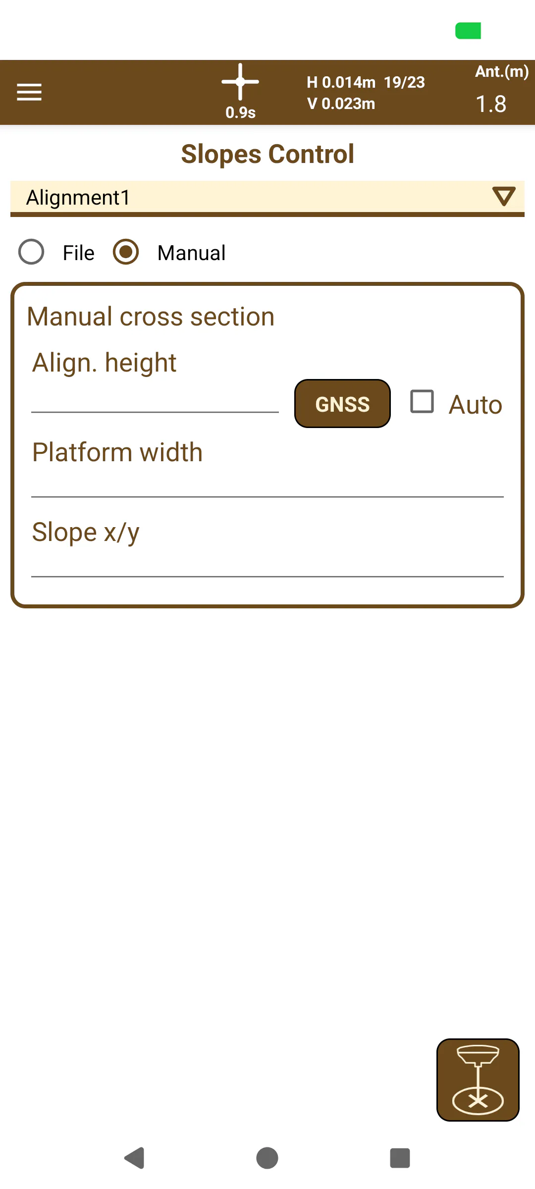 |
|---|---|
Figure 140. Slopes Control by File | Figure 141. Manual Slopes Control |
The first step to configure the slope control that you want to perform is to select choose between a file and a manual cross-section.
When using a cross-section file, the cross section to be used in the process has to be selected. Once this is done, the following options will be activated:
Setting out through codes: If you want to set out according to a certain segment template of the template, you can select the codes of the points in each end of a certain template. In this way, the control will be referred to the vector that defines the stretch and its extension in space. If this option is not selected, the control will be done according to the entire selected template.
Height dimension: If the height dimension is taken automatically, the control will be referred to the current template dimension. If a point of the template is selected as the reference dimension, it will be determined by entering the code of that point or selecting it from the template itself.
To select the codes in each case from the selected template, press the button  . In this way, the template closest to the current position will be displayed or you can travel between the template to look up the required code directly on the models.
When using manual cross-section, by inputting manual information, it is possible to create a simple cross-section to use for Slopes Control by adding 3 data points:
Alignment Height: Obtained manually by typing it with the keyboard, using the receiver’s current altitude (GNSS button), or automatically using the grade by selecting the “Automatic” checkbox.
Platform Width: Creates a symmetrical flat platform base with the indicated width in meters.
Slope x/y: Creates a slope from the platform with the indicated inclination with the slope ratio x/y (0, 0.5, 1, etc)
Slope control display
In the slope control display screen, the elevation of the template closest to the current position of the GPS and the information related to the movements to be made to reach the position in said slope is presented.
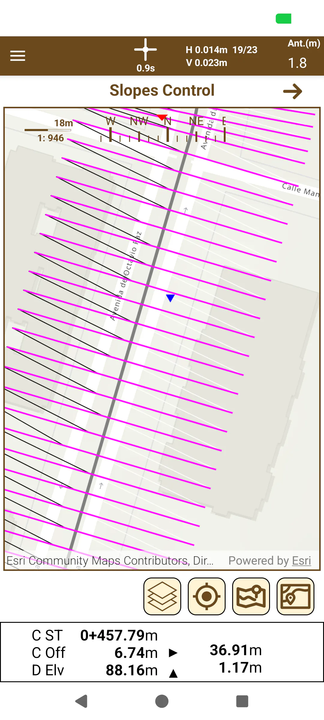 | 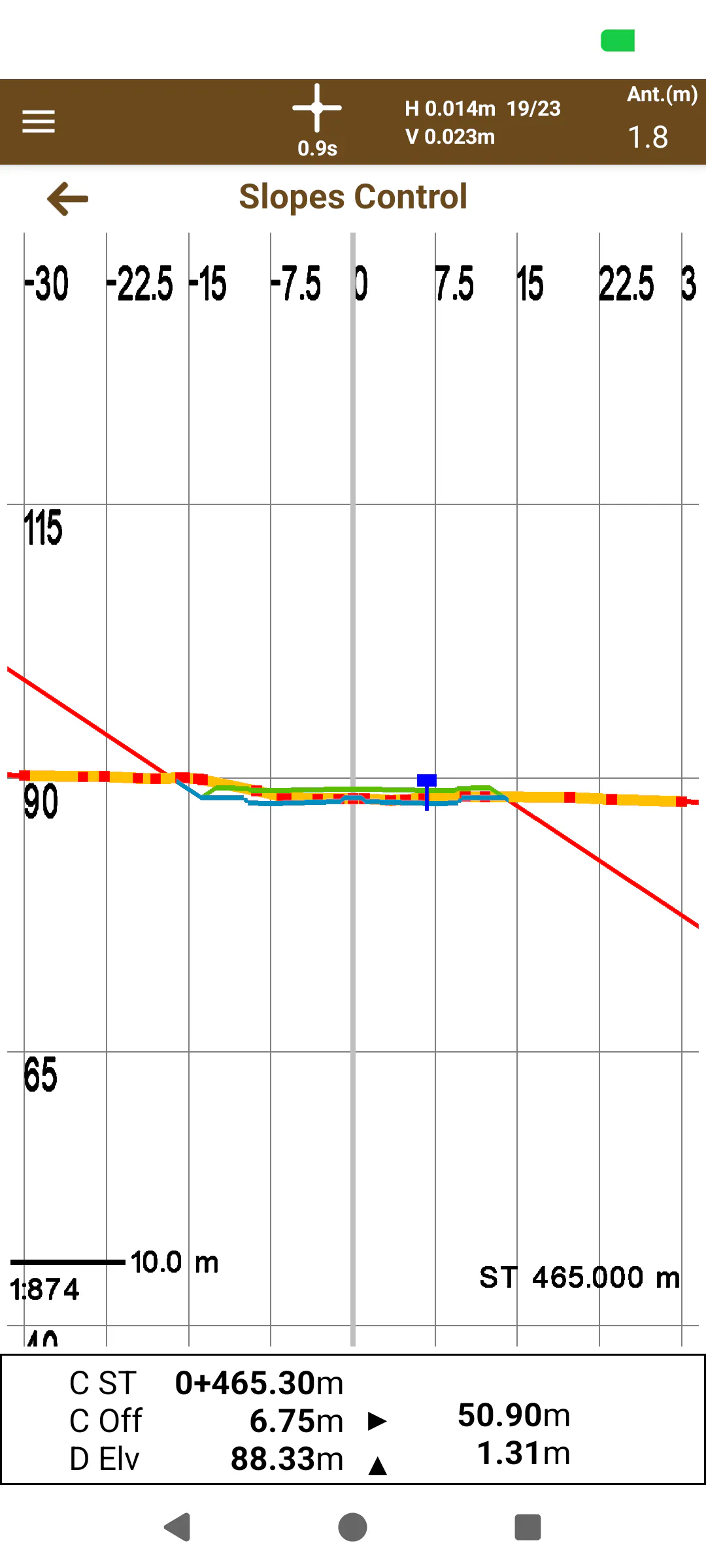 |
|---|---|
Figure 142. Slope control display (top view) | Figure 143. Slope control display (front view) |
The information displayed is the following:
The Station and the current displacement.
Movement in / out of the horizontal alignment to reach the slope.
Current elevation and movement up / down to reach the slope.