tcpMDT Photovoltaic
Convert structures - PV25
2.9 CONVERT STRUCTURES
Trackers
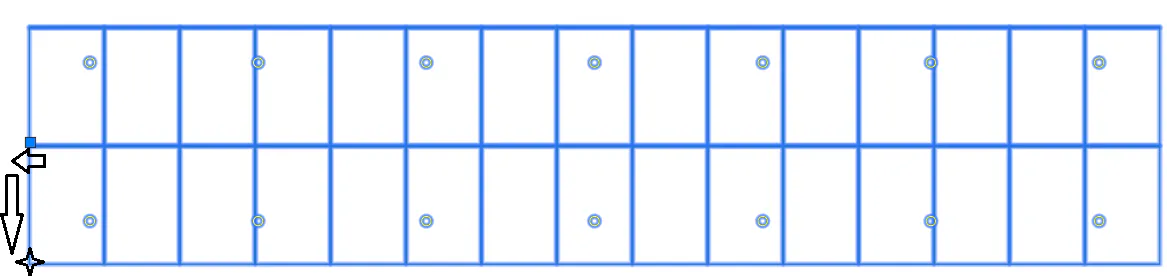
This command will allow us to automatically convert a set of closed polylines that represent trackers to project trackers.
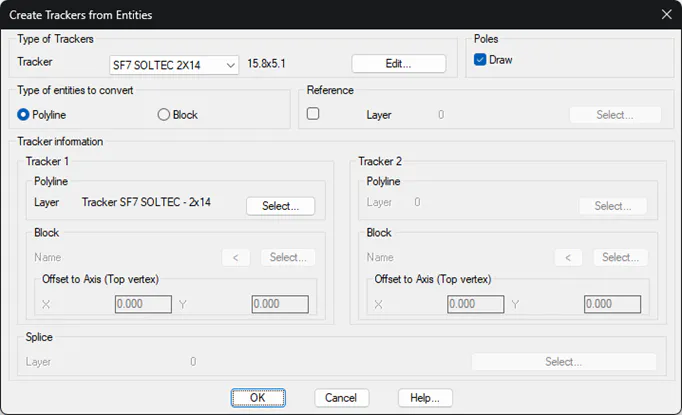
Initially, the following window will appear in which we will configure the input data to carry out the conversion.
Type of Tracker
Tracker: Select the type of tracker to convert from the drop-down menu. This list will list all previously defined types of trackers.
Edit: Allows us to get into the definition of Tracker Types. This option is described in detail in a previous section.
Draw Poles: Enabling this option will automatically draw the poles of the converted trackers.
Reference: When you enable this option, the software will read the existing texts on the selected layer and assign the corresponding text as a Reference to each tracker. This text must be contained within the tracker.
Depending on the type of tracker selected, the Tracker 1 or Tracker 2 options will be enabled. In the case of selecting a dual-row type of tracker, both will be enabled, otherwise, only Tracker 1 will be enabled.
Tracker Information
Polyline: The features to be converted are closed polylines.
Block: The entities that represent the trackers are block type entities.
Polyline: Selection of the layer on which the polylines that we want to convert to trackers are located. It is advisable to place the polylines to be converted in a single layer, so that the conversion will be done more quickly.
Block:
-
Name: Name of the block, by pressing the Select button, when selecting any of the blocks that the tracker represents, the name of the block is automatically read.
-
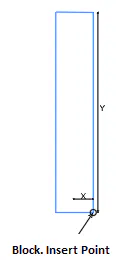
Offset to Axis: These parameters will be considered depending on the type of block, in any case, the information to be provided would be the following:
-
X: Signed distance from the block's insertion point to the midpoint on the top side
-
Y: Signed distance from the block's insertion point to the top vertex of the block.
Once the conversion is done, the number of converted trackers and the zones in which they are located are reported on the "command line" of the CAD. They will automatically be drawn with the color defined in the template, as well as their corresponding poles.
Fixed Structures
With this command we are going to convert the drawing entities to the necessary object of the software to work with Fixed Structures. With this type of structure, it is necessary that the entities to be converted are represented as blocks.
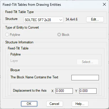
Structure: We select the type of structure that will be used as a reference to perform the conversion. In this case, it is necessary to select and structure of the Fixed Table type. With the "Edit" button there is the possibility to modify the characteristics of the selected structure type before performing the conversion.
Type of Entity to convert: Currently for Fixed Structure projects it is only possible to work when they are represented as blocks.
Structure Information.
Block: It is necessary to enter the name either in full or in part of the block that represents the Fixed Structure. The fact of entering it partially helps that, in the event that there are several blocks with names where they partially coincide in the same, the conversion is carried out together.
Axis Displacement: Displacement of the insertion point of the block to the lower left vertex of the block.
X: Displacement in X with its sign.
Y: Displacement in Y with its sign.