
tcpMDT Photovoltaic
Types of structures - PV25
2.8 TYPES OF STRUCTURES
In this section we define the library of trackers, which will serve as a template for the conversion from drawing.
Initially, the following window will appear in which, by default, there are already a series of defined types of trackers.
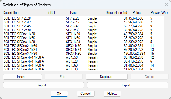
With the Insert, Edit, Duplicate and Delete buttons, we manage the library of trackers.
Import
With this option, we have the possibility to import a file of Types of Trackers (tpseg extension). They will be added to the existing ones.
Export
With this command, we will export the Tracker Types selected in the list, to a file (tpseg extension). The list allows multiple selection.
To insert or edit a type of tracker, the following window will appear, which we will now describe.
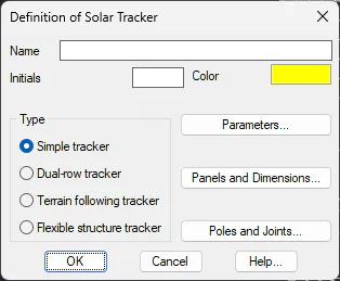
Name: Name associated with the type of tracker.
Initials: Brief description of the type of tracker to be defined.
Color: Color of representation of the tracker in plan.
Type: There are three types of trackers with which the software has the possibility of working:
-
Single-row or Simple tracker.
-
Dual-row tracker.
-
Terrain following tracker.
-
Flexible structure tracker
Depending on the type of tracker selected, its own characteristics will be defined.
Simple Tracker Parameters
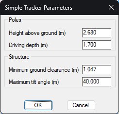
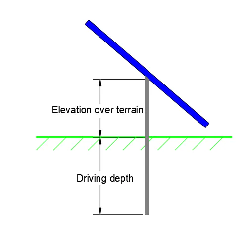
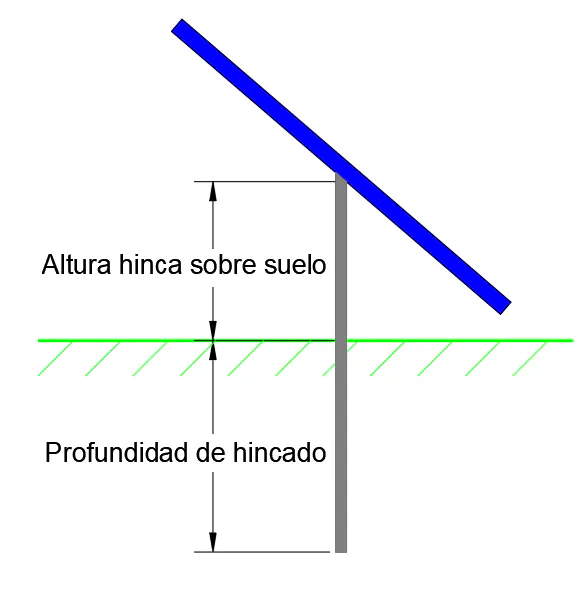
Height above ground (m) : The height of the tracker brackets above the field.
Driving depth (m) : Maximum depth under the ground of the tracker poles.
Minimum ground clearance (m): This parameter is what is known as nominal clearance, it defines the minimum distance of the plate at its angle of maximum inclination with respect to the ground.
Maximum Tilt Angle (degrees): We indicate the maximum tilt angle of the tracker.
Dual-row Parameters
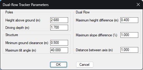
Height above ground (m) : The height of the tracker brackets above the ground.
Driving depth (m) : Maximum depth under the ground of the tracker poles.
Minimum ground clearance (m): This parameter is what is known as nominal clearance, it defines the minimum distance of the plate at its angle of maximum inclination with respect to the ground.
Maximum Tilt Angle (degrees): We indicate the maximum tilt angle of the tracker.
Duo. Maximum height difference (m): This is the maximum elevation difference that can exist between the two trackers that make up the dual-row structure.
Duo. Maximum slope difference (%): It is the maximum longitudinal slope difference between the two trackers that make up the dual-row structure.
Duo. Distance between axis (m): In case the dual-row tracker is inserted with the "Insert Tracker" tool, set the separation between the two trackers.
Terrain Following Tracker Parameters
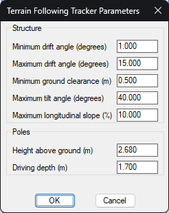
Minimum drift angle (degrees): We establish the minimum permissible angle for the vertices of the Terrain Following Tracker. Below this value, it is considered that it is not necessary to insert the joint.
Maximum drift angle (degrees): We set the maximum allowable angle at the tracker's joints. Above this value, a restriction notice will be generated.
Maximum longitudinal slope (%): Establishes the maximum longitudinal slope that each of the sections of the articulated tracker can have. Slopes above this value will generate a constraint.
Minimum ground clearance (m): This parameter is what is known as nominal clearance, it defines the minimum distance of the plate at its angle of maximum inclination with respect to the ground.
Maximum tilt angle (degrees): We indicate the maximum tilt angle of the tracker.
Height above ground (m) : The height of the tracker brackets above the field.
Driving depth (m) : Maximum depth under the ground of the tracker poles.
Flexible Structure Tracker Parameters
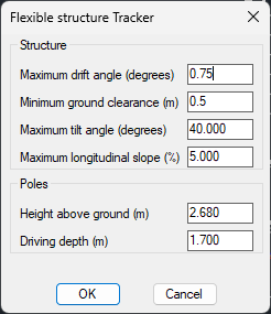
Maximum drift angle (degrees): We set the maximum allowable angle at the tracker's joints. Above this value, a restriction notice will be generated.
Maximum longitudinal slope (%): Establishes the maximum longitudinal slope that each of the sections of the articulated tracker can have. Slopes above this value will generate a constraint.
Minimum ground clearance (m): This parameter is what is known as nominal clearance, it defines the minimum distance of the plate at its angle of maximum inclination with respect to the ground.
Maximum tilt angle (degrees): We indicate the maximum tilt angle of the tracker.
Height above ground (m) : The height of the tracker brackets above the field.
Driving depth (m) : Maximum depth under the ground of the tracker poles.
Fixed Structure Parameters
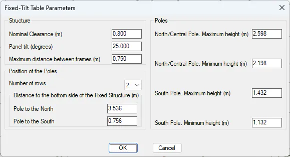
Nominal clearance (m): Minimum distance from the lowest end of the panel to the ground.
Panel Tilt (degrees): Tilt in degrees of the panel.
Maximum distance between frames (m): In the conversion of each of the blocks of the tables, the minimum distance between them so that they can be analyzed together.
Number of rows: Number of rows of supports, currently one or two rows are supported.
Distance to the lower side of the Structure. Pole to the North (m): Distance from the northernmost row of supports to the south side of the structure.
Distance to the lower side of the Structure. Pole to the South (m): The distance of the southernmost row of supports of the table from the southernmost side of the structure.
North (Central) Pole. Maximum height: Maximum height of the pole north of the structure, or of the only pole in the case of a single row.
North (Central) Pole. Maximum height: Minimum height of the pole north of the structure, or of the only support in the case of a single row.
South Pole. Maximum height: Maximum height of the stand south of the table.
South Pole. Maximum height: The minimum height of the stand south of the table.
Panels and Dimensions
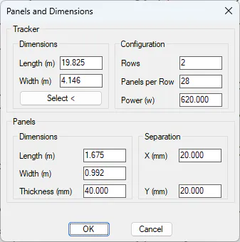
Dimensions: These parameters are very important as they are the values that will be taken as a reference when converting from the existing drawing. It will consider the entities that fit the specified Length and Width.
Select: With this action we have the possibility to graphically select the type of tracker and the length and width of the tracker will be automatically calculated.
Number of rows: The number of rows of tracker panels.
Number of panels per row: The number of panels that exist in each row of the tracker.
Power (Wp) : Power of each of the tracker panels.
Panels. Dimensions.
Length (m): Length of the photovoltaic panel.
Width (m): Width of the photovoltaic panel.
Thickness (mm): Thickness of the photovoltaic manel.
Separation. X (mm): Longitudinal spacing between panels.
Separation. Y (mm): Transverse separation between panels.
The parameters of the Panels are used for export to PVSyst software.
Poles and Joints
It allows us to edit the distribution of the poles and joints along the tracker.
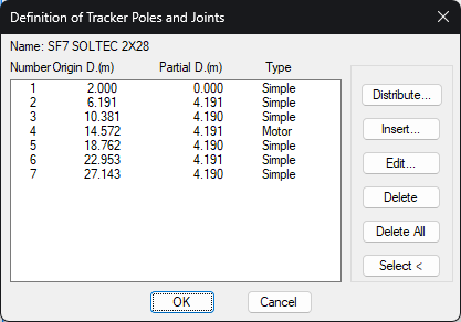
Distribute: With this action we can insert a certain number of poles equidistant from each other. In the case of terrain following trackers, it will allow us to insert the joints in the same way that the poles are inserted.
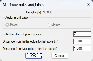
Total number of poles/joints: Number of poles that the tracker will have.
Distance from initial edge to first pole (m) : Indicates the distance between the starting vertex of the tracker and the position of the first pole.
Distance from last pole to final edge (m): Indicates the distance between the last pole and the trailing vertex of the tracker.
Validating this window will automatically insert the poles. By default, the center pole is defined as Motor type. In the drawing it is distinguished by the fact that it is represented by a square and the rest of the poles by a circle.
Insert: Allows us to insert a pole at a certain distance from the initial vertex of the tracker.
Edit: Edit the properties of an already defined pole.
Delete: Removes the designated pole.
Delete All: Removes all poles.
Select: Prompts us for a polyline and inserts a pole at each of the vertices of the selected polyline.