
tcpMDT
Import IFC - MDT25
24.4 Import IFC
When executing the command, it will initially request the IFC file, once selected, the following window will appear in which both the characteristics of the project itself and its contents are displayed.
This option offers us the possibility of importing each of the elements.
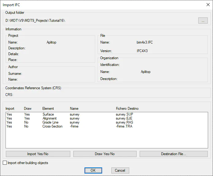
Information: All the information contained in the IFC file and related to the project is shown.
In the list we will see the different elements that the file contains, in this case, it contains a surface, a horizontal and a vertical alignment.
Import Yes/No: We select the element we want to import.
Draw Yes/No: We indicate if after the import, we want the imported element to be drawn automatically.
Destination File: We select the name of the destination file of the element to be imported.
Import other building objects: If we activate this option, the IFC file to be imported will be analyzed and those elements that have their own representation will be imported as 3D Faces of the CAD, regardless of the elements of roads, such as Alignments, Surfaces and Grades.
The following objects are currently processed if they have a 3D representation:
-
IfcBuildingElementProxy
-
IfcSite
Once the dialogue has been accepted, the elements will be imported and drawn if appropriate.
Additionally, if the item to be imported has properties assigned, these will be imported automatically. These properties will be saved in an XML file with the same name as the imported file and .prop extension.
To consult the properties assigned to any element (alignment, surface ...) we have the command BIM > Property Assignment.
Export IFC
This command will enable you to export the content of our project to an IFC file. When first executing the command, the following window will appear in which you select the elements to be exported.
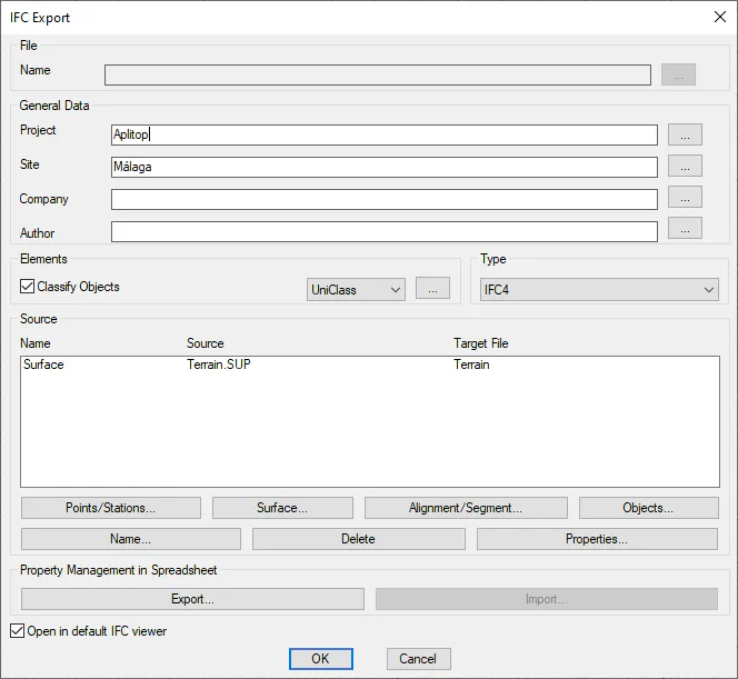
File
It allows us to give our exported IFC file a name according to the BIM Nomenclature, for this we press the button with the three dots and it shows us the corresponding dialog to select in each case the option that best suits our work and the state of it.
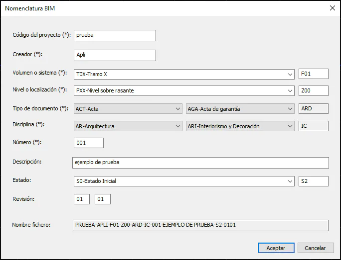
On the website https://www.buildingsmart.es/recursos/nomenclatura-documentos-bim/, we can download a manual on BIM Nomenclature.
General Data
We provide details of the characteristics of the project such as the name, company, location.... All the fields described below are optional and their specifications are not required to generate the IFC file.
Each of the characteristics is described below.
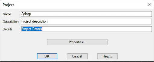
Project: You enter the name of the project. Clicking on the (...) button will enable you to specify more details of the project to be exported.
-
Name: Name of the project - the same value as that in the main IFC import window.
-
Description: A description of the characteristics of the project.
-
Details: • A field in which to provide an additional description.
-
Properties: The option of assigning certain properties to the project to be exported. For more details, execute BIM > Definition of Properties Sets or BIM > Assign Properties.
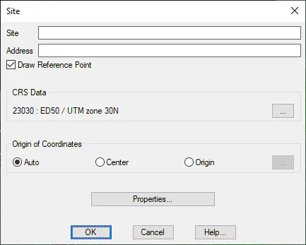
Place: This space is reserved to specify the place or location of the project to be exported. Clicking on the (...) button will enable you to access its specification.
-
Place: Description of the place at which the project is being executed.
-
Address: The address or location of the project.
-
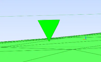
Draw Reference Point: If we activate this option, a pyramid will be drawn marking the selected reference point in the "Origin of Coordinates".
-
Coordinates Reference System (SRC): The reference system in which the project to be exported is located.
-
Origin of Coordinates: You can configure the origin of the coordinates for the project to be exported.
-
Automatic: The coordinates of the project itself by default.
-
Center: The center of the surface to be exported is established as reference coordinates.
-
Origin: Selection of specific coordinates in the drawing.
-
Properties: The option of assigning certain properties to the Place to be exported. For more details, execute BIM > Definition of Properties Sets or BIM > Assign Properties.
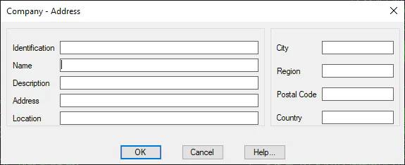
- Company: This section indicates the details of the company to which the project to be exported belongs. In the same manner as in the previous options, clicking on the (...) button will enable you to access its specifications.
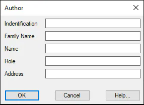
Author: Details of the author of the project.
Classification of Objects
MDT provides the option of classifying the different objects to be exported. These classifications have been generated by different entities and we now have the option of classifying them in accordance with these two standards.
-
UniClass
-
guBIMClass
You can personalize these classifications and add new ones under Settings > BIM.
Once the entity has been selected, clicking on the (...) button will enable you to access the classification of the different objects.
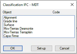
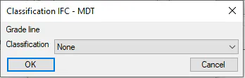
Double-clicking on any of the objects will provide access to a new window in which you will have the option of assigning the corresponding code.
Clicking on the Settings button will provide access to the editing of the classifications file; for more details access the BIM > Classifications command.
Version
IFC has different versions of the format; MDT currently supports the following versions:
-
IFC 2X3
-
IFC 4
-
IFC 4X1
-
IFC 4X3
Management of files to be exported
Points/Stations: Selection of the Points or Stations file to be exported. In Utilities > Configuration > BIM,it is possible to customize the shape of the Point or Station to be exported.
Surface: You select the surface file to be exported, and it is possible to select several surfaces.
Alignment / Segment: If you select a segment and it has defined pavement layers, these pavement layers will also be exported to the IFC format together with the segment grade line.
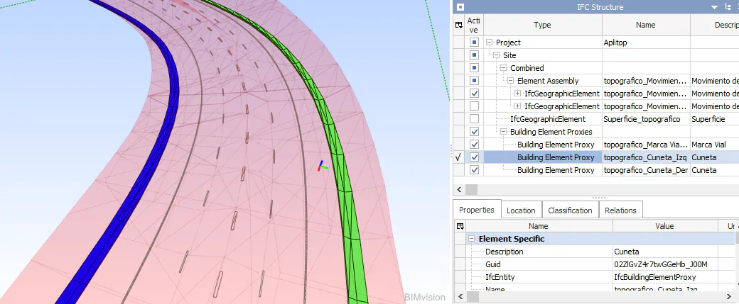
In the event that the ditch of our section has a coating thickness, it will be modeled by applying a texture for visualization, in the following image you can see a definition of ditches on both sides of the axis.
Objects: From this option we have the possibility to export to IFC the outline of closed polylines. To do this, the polylines to be exported must be found at the height we want to show.
This option is particularly useful if we want to show horizontal signals in our IFC file, for example, pedestrian crossing, direction arrows ...
It is managed with the following window:
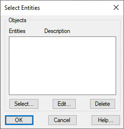
With the "Select", "Edit" and "Delete" buttons we manage the list of objects.
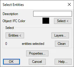
If we press the "Select" or "Edit" buttons, the following window will appear from which we will select the objects or polylines to export.
-
Description: Comment that we want to associate with the set of selected entities or polylines.
-
Object IFC Color: Color with which the objects will be displayed in the IFC file.
-
Select: Mode of selection of entities or polylines
-
Entities: Graphic selection.
-
Layers: Selection of polylines contained in one or more layers.
-
-
Properties: Ability to associate properties with selected entities. these properties will be exported as properties sets of the objects exported to ifc.
Networks: When you run the command, it will automatically detect the existing Pipe Networks in the drawing and give you the ability to export it to IFC. You will assign the network features as the Properties Set of the IFC object.
Delete: You delete one of the elements selected for export.
Name: The name assigned to the element in the IFC file to be exported. It can be changed.
Properties: If the element selected from the list has assigned properties, this option we will enable you to view them and change them. See BIM > Assign Properties for more details on assigning properties to elements.
Signage
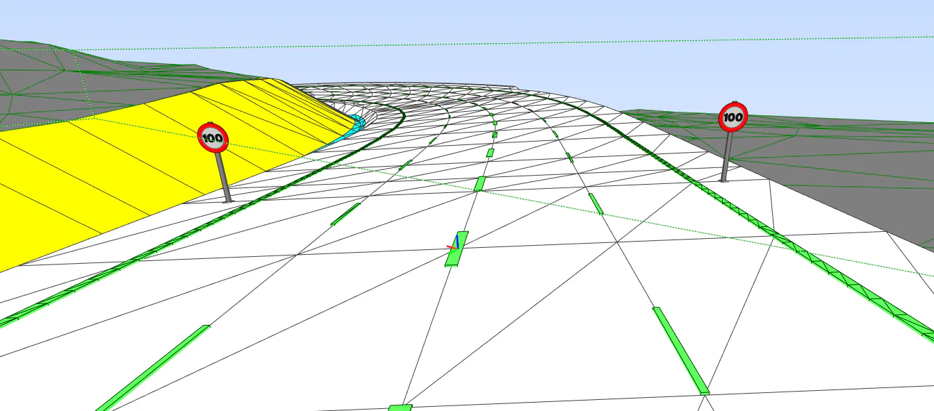
TcpMDT has the possibility to export to IFC both vertical and horizontal signage for a given segment or road.
-
Señalización horizontal o marcas viales: To do this, in the definition of Templates, in the section of Road Marks, we specify the type of mark for each of the vectors of the section. Once this section is configured, they will be automatically exported to IFC without any additional steps.
-
Vertical signage: Prior to exporting to IFC, it is necessary to insert the vertical signage in the drawing, for this use the option of Maps -- Realism > Insert 3D Object, once the signals are inserted, when executing this option, in the export window to IFC automatically, an entry with the name "Vertical Signaling" will appear as an element to export.
Open in default IFC viewer
In the event that we have a file viewer installed, once exported, it will automatically open the associated software.