
tcpMDT
Export to kmlkmz - MDT25
23.9 Export to KML/KMZ
This MDT command allows you to generate a KML file and then view it on Google Earth. The coordinates of the elements to be exported must be projected coordinates. If these requirements are not met, when viewing the file it will appear in the wrong place on the planet. You can also specify a plan offset, which will be applied to all the coordinates that are included in the file.
Initially, a dialog appears where you can select the elements to include in the export. The projection will be displayed by default in the event that the drawing has one assigned.
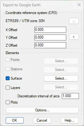
Once the elements to be exported have been selected, the program requests a file where the information can be stored. It should be noted that a KML file is less efficient in size and speed than its DWG equivalent. Therefore, depending on the characteristics of the computer, if many elements are exported, Google Earth may not be able to open the resulting file.
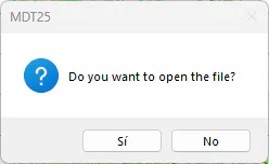
Finally, if the question of whether you want to view the file is answered in the affirmative, Google Earth will run if it is installed on the computer. More details of the various exportable items are given below.
Points
Activating the option Points, all points in the drawing are selected by default, and the corresponding Select button allows you to choose a smaller set. On the left panel of Google Earth, they will be seen inside the Points folder. By enabling or deactivating the folder flag, you control whether the elements it contains are visible. By displaying the content, visibility can be activated individually for each point.
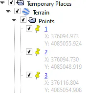
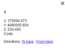
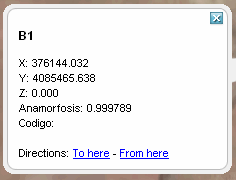
By clicking on the name of the point, you can see in a floating window the details of the point, and by double-clicking the image is centered around those coordinates.
Stations
The export of bases is similar to that of points, with the particularity that the anamorphosis of the base is included among its details.
Surface
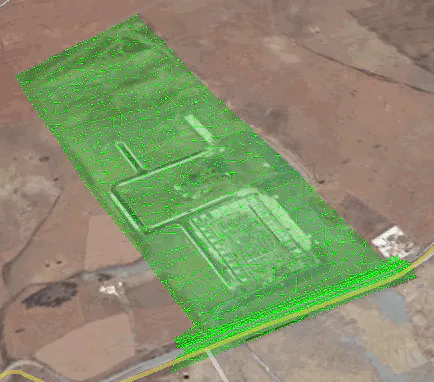
When you export a surface, an object is created that includes all the triangles on the surface. In case of having executed earthmoving commands, or obtaining modified terrain, the surface is divided into several objects, which reflect esplanades, clearings, embankments, etc.
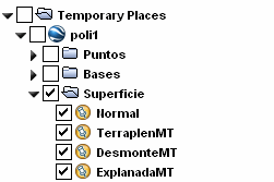
Below the list of elements, when you select a surface, a control appears that allows you to adjust the transparency of the graphical representation.
Layers (Polylines)
Each of the selected layers appears in the left pane of Google Earth as an element. Only layers that have polylines are included, and all of them are represented by the same color, the color of the layer.
Plots
Entities created with the Plots commands are exported individually. In the left pane of Google Earth, inside the Plots the name of each of them appears, including the associated details of Area and if they exist Owner and Reference.
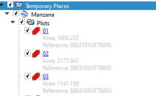
In an identical way to the points, clicking on the name of the parcel brings up a floating window with the details.
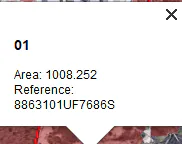
In terms of graphical representation, plots are shown as a closed polyline filled with color, similar to how surfaces look.