tcpMDT
Drawing profiles of pipes - MDT25
20.3 Drawing Profiles of Pipes
Next, we are going to represent the profiles of pipes, and in this case, we are going to represent the sewerage network pipe located further north.
We then execute the Pipe Networks > Draw Profile of Pipe command and select the pipe of the sewerage network located further north in the drawing.
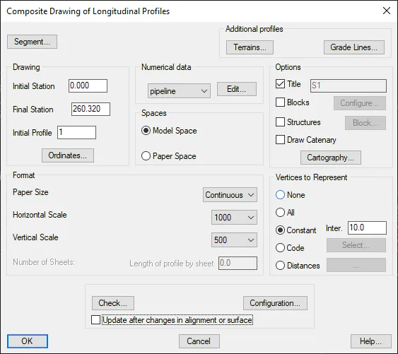
The following window will appear in which to configure the presentation of the profile, and we validate the default values. We indicate that we do not want to represent specified distances.
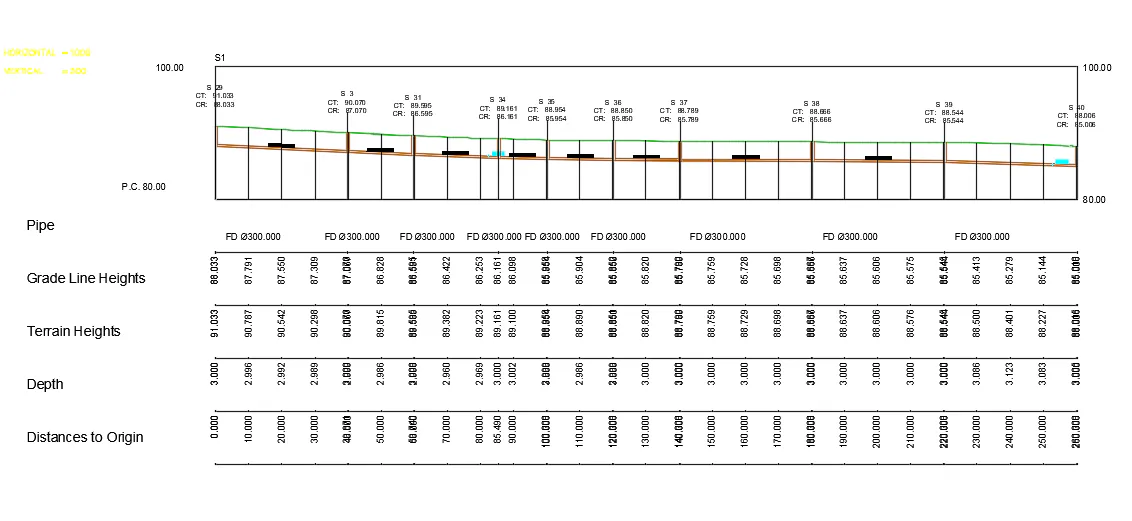
The end result is illustrated in the screenshot below:
Zooming in on node S_34 in the elevation representation will enable us to see the intersection with one of the rainwater pipes.
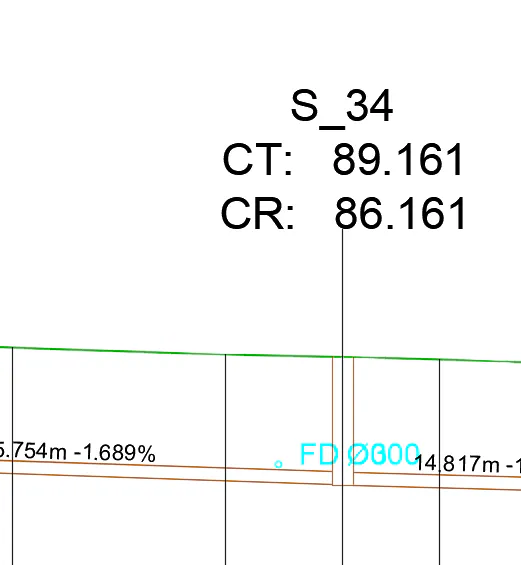
In order to prevent both pipes overlapping, we edit node S_34 and change its depth to 3.5. To do this we execute the Pipe Networks > Edit Node command, select the Front option, designate the pipe in front view and then the node to be edited.
The following window will appear in which we change the depth value to 3.5, after which the profile will be updated automatically.
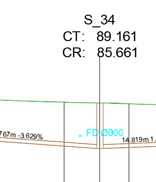
In a similar way, we proceed with the nodes specified below to maintain the downward slope of the piping section.
If we look for node S_34 on the plane, we will see it has been automatically updated after the change in the elevation.
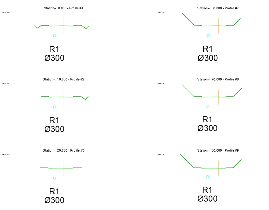
Finally, we are going to project one of the networks on some previously generated cross-section profiles, which will be very useful for locating the position of the piping network in the cross-sections in elevation mode.
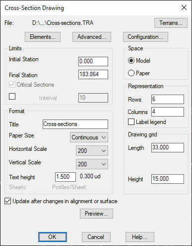
To do so, we execute the Cross-Sections > Draw Cross-Sections (or Cross-sections> Drawing> Draw) command and select the CrossSections.tra file. We then validate the drawing window with the following parameters:
We then execute the Pipe Networks > Draw Cross Sections of Pipe command, select the section of rainwater piping located further East, any of the cross-section alignments and the alignment from which the cross-sections have been generated, Alignment.eje, we can select this file from the example folder. The result is as follows: