tcpMDT
Defining elements - MDT26
To perform this exercise, you must have MDT Professional Version.
In this example, we will describe the fundamental tools of the alignment calculation command.
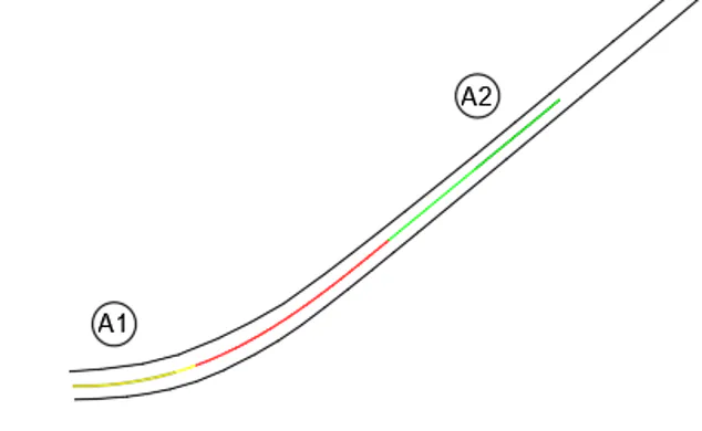
First, open the Alignments.dwg file in directory C:\MDT26_Projects\Tutorial13. In the drawing, there are two white lines, which represent an existing path, and some lines and arcs that we have identified, that we will use to build an alignment that passes nearly through the center of existing path, from left to right.
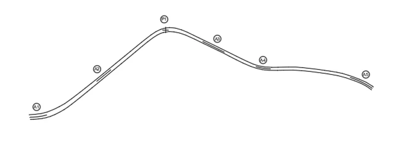
13.1 Defining Elements
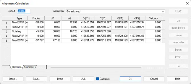
Run Elements > Calculate and select arc A1 located to the left of the drawing. A window will appear in which you can see the alignments that we will use to design the alignment.
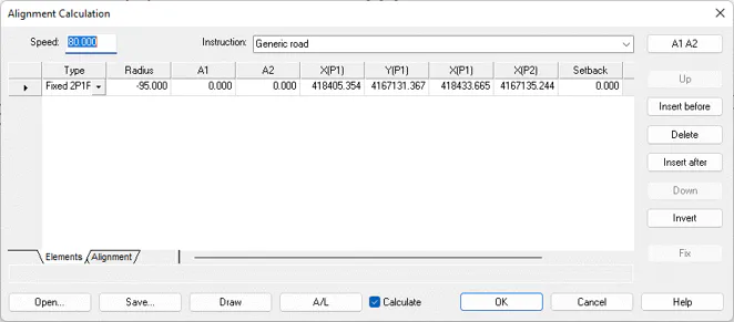
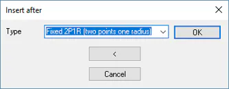
Press the Insert after button and press the button < to name and select line A2, located inside the path.
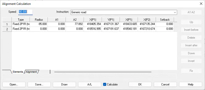
The program automatically calculates the transition clothoid between the line and the contour, and assigns parameter A2 (the output clothoid) to element number one.
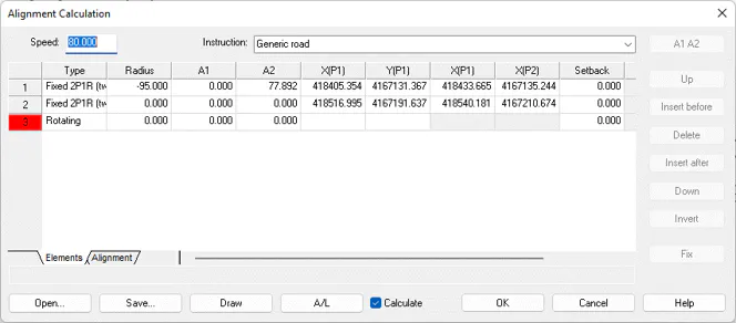
Then, we select the second element, clicking on any column. An arrow appears to the left of the row confirming the selection. By pressing the Insert after button, in the list select Rotating and press OK. In the list, element 3 appears in red, indicating that it has not been calculated yet.
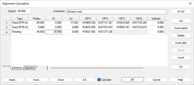
By clicking on its corresponding box X(P1) of the third row and the button ..., we select the point P1 using node CAD object snap reference, and enter a radius of 45 and a parameter A1 of 30.
Now we select again the third element in the list, press Insert after, and we select the next line A3. We repeat the process with element 4, selecting the left end of the next line A4. The program automatically calculates the clothoids that enable the alignment continuity.
After element 5, with Insert after, we select from the Floating list and press OK. In order to calculate the floating element, there must be elements calculated before and after. Pressing again Insert after we select the next arc A5. We can see that in the drawing, we have calculated a floating line, which is not of interest. We have a better solution changing the mobile radius to 400.