tcpMDT
Defining roadbed from drawing - MDT26
To perform this exercise, you must have MDT Professional Version.
The objective of this exercise is to define the roadbed surface and the roadbed layers associated with a road, as well as the calculation of the volumes of each of the roadbed layers.
To begin, we will define the section from a polyline in elevation which represents the final state of our section. First, we open roadbed.DWG drawing inside folder C:\MDT26_Projects\Tutorial10.
10.1 Defining Roadbed from Drawing
We execute the command Templates> Create from Polyline in Profile View. We create a new file roadbed.SCC, then, we select roadbed.EJE file as alignment and finally the polyline of the drawing, which is going to be our type section.
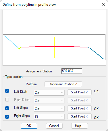
Then the following window will appear, where we will indicate the starting point of each one of the section elements by pressing the corresponding buttons to each section element. As an aid, we can use the reference methods to CAD objects (end point, midpoint, etc.).
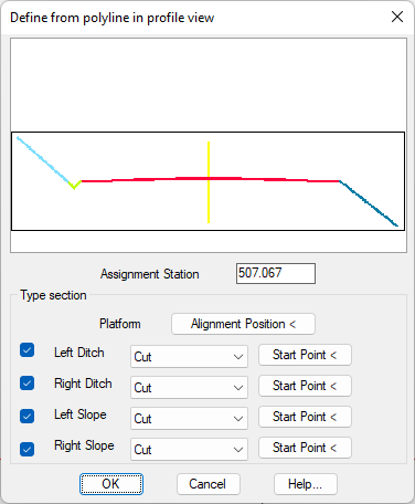
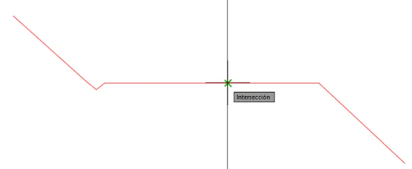
Platform: We will indicate as alignment position, the intersection of the vertical line with the platform.
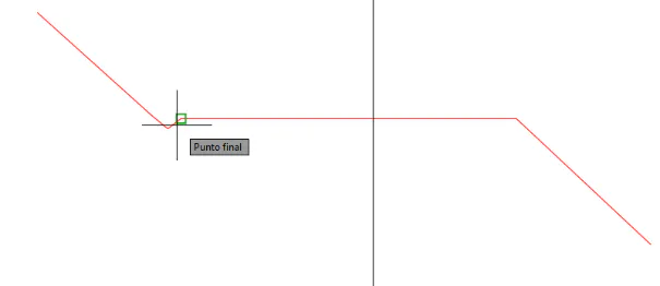
Left Ditch: We indicate as the point of attachment, the end of the platform. It will be applied only in Cut.
Right Ditch: We uncheck this option, since there will be no ditch on the right side.
Left Slope: As with the left ditch, we indicate the point of attachment at the end of the ditch. This would be a cut slope.
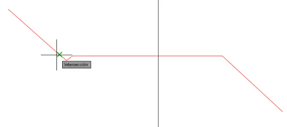
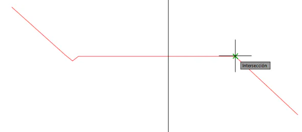
Right Slope: We indicate the point of attachment at the end of the platform on the right side. This would only apply to fill slope.
The final data window status after selecting all the elements would be as follows:
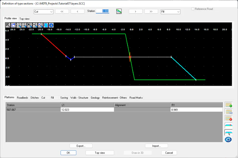
The program has automatically assigned the names L1 and R1 to the platform vectors. Therefore, before defining the roadbed, we change their name to Lane1. This can be done by selecting the name of the vector with the right mouse button and running the Change vector type option. The final result would be the following: