
tcpMDT
Defining reinforcements - MDT26
9.2 Defining Reinforcements
Once the segment has been defined, we are going to modify the road type section so that it considers the existing road surface, aimed at making use of the roadbed.
To do this, run the command Templates> Create/Edit (or Templates> Create> Create/Edit), select solera.SEG segment.
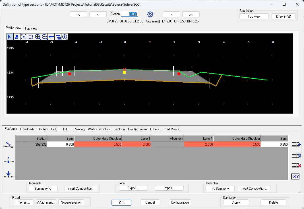
Click on Reinforcement-- Others tab, then we check the Apply box, and establish -0.5 and 0.5 meters as tolerance values for Minimum Dif. and Maximum Dif. respectively. The value corresponding to the roadbed thickness. As the objective is the full use of the existing roadbed, check the Adjust to terrain box.
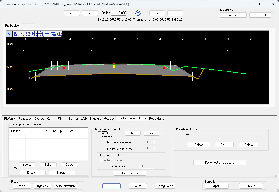
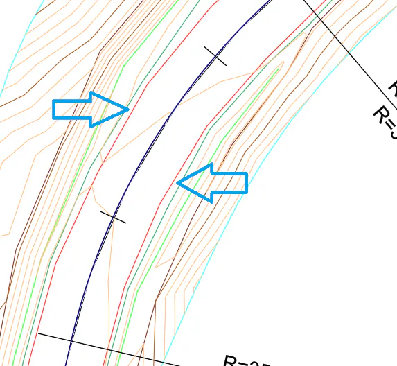
Finally, it is necessary to indicate the new road where the existing road is located. For this, we press the Select Polylines button and select the two blue polylines that define the boundary of the platform.
Automatically, if we move forward in the different existing stations, we will observe how, in certain stations, there are two red marks, indicating the point where the road takes place and how the type section will adapt to the existing road.
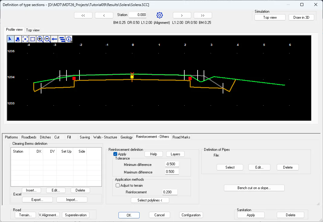
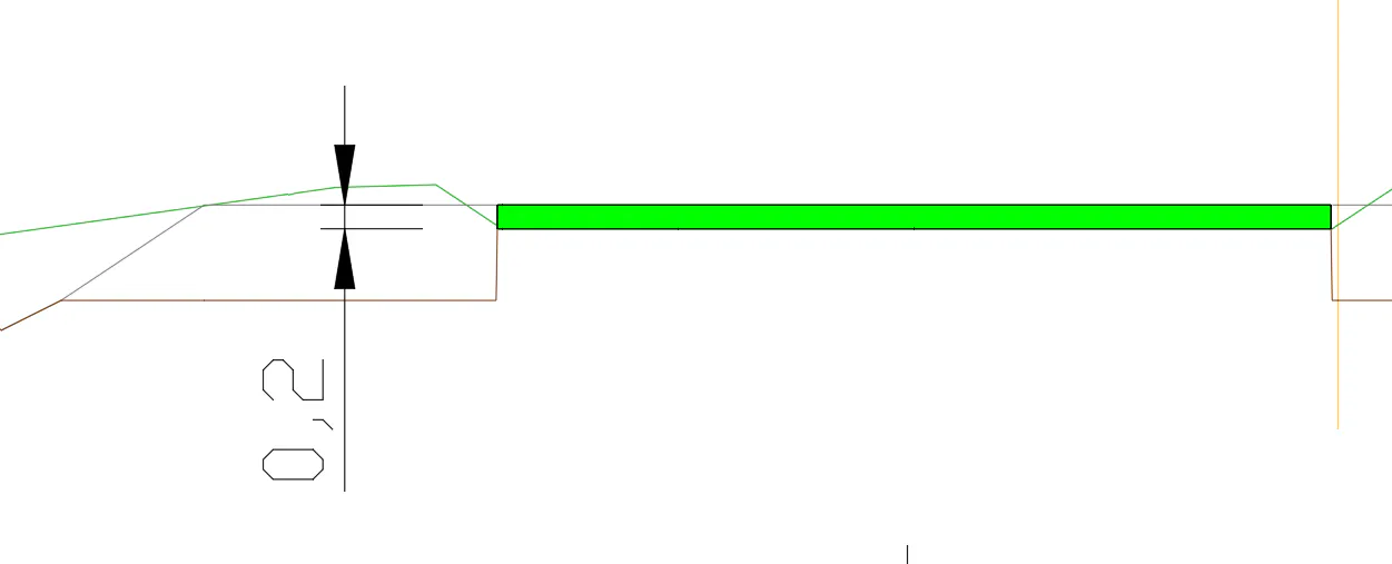
Additionally, since we need that in the area to be reinforced there is at least a roadbed layer of 20 centimeters, in Minimum thickness we establish the value 0.2.
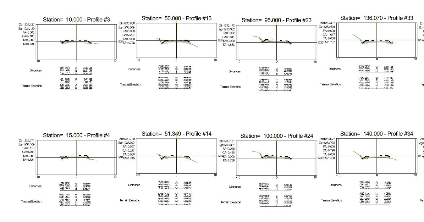
Then, we can draw the segment from the Cross-Sections> Draw Cross-Sections (or Cross-sections> Drawing> Draw) option by selecting the solera.SEG file. In the drawing, we can clearly see the use of roadbed that is made in certain stations. In this case, we are going to draw with Paper Size in Continuous, Horizontal and Vertical Scale at 500.
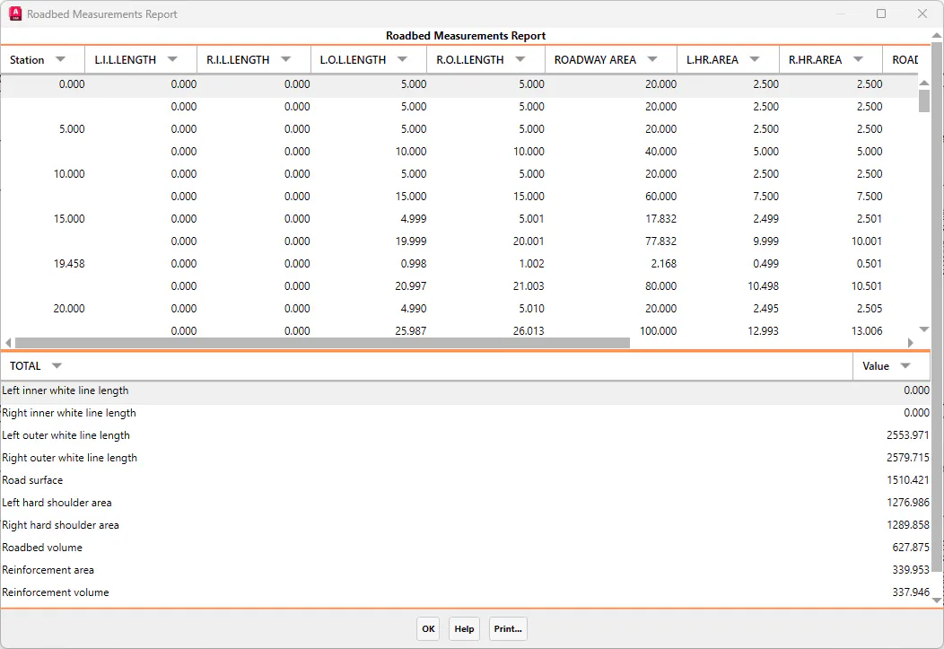
Finally, we can obtain a list of volumes where the reinforcement area and volume is reflected. To do this, we run the command Quantity Takeoff > Areas > Roadbed Measurement Report (or Quantity Takeoff> Roads> Areas> Roadbed Measurement Report), select the solera.SEG segment and validate the window with the default data that appear on the start station and end station.
After carrying out the calculation process, the following list will appear, in which different concepts are reflected, among them, the reinforcement areas and volumes.
File Overview
Once the job is finished, we list the existing project files in the C:\MDT25_Projects\Tutorial09 directory. The main files are the following:
File Description
solera.dwg Drawing with the existing ground
solera.sup Surface file
solera.seg Segment file
solera.lon Long section file
solera.ras Vertical alignment file
solera.scc Template file