tcpMDT
Creating pipes - MDT26
20.2 Creating Pipes
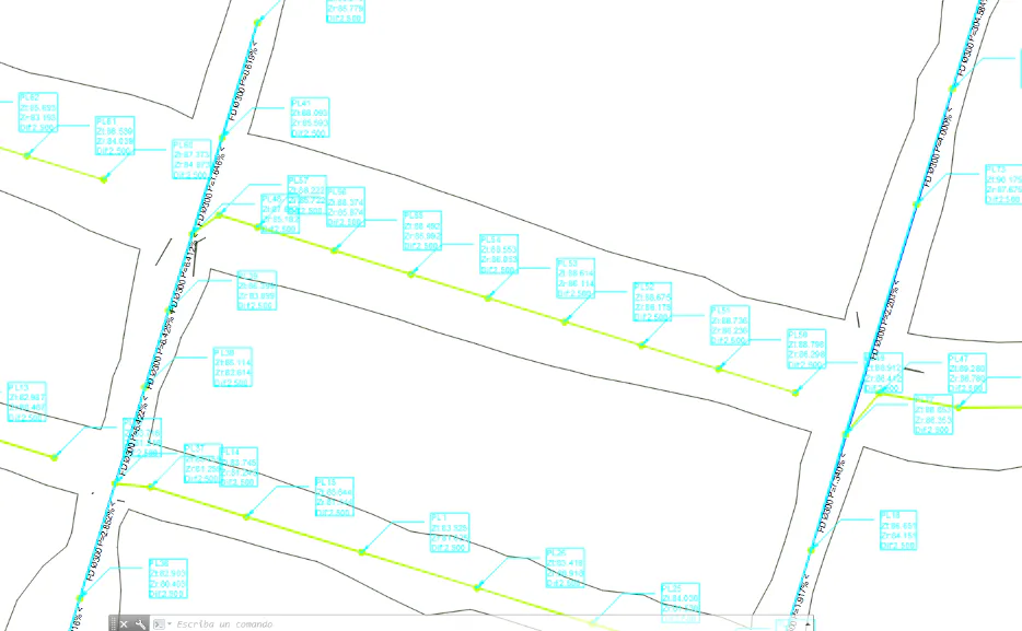
Once the sewerage and rainwater network nodes have been created, we now create the pipes. Due to the fact the creation of the entire network would take us some time, we are going to define, in the case of the sewerage network, the pipes corresponding to the polyline in orange. Set as active layer 0 and hide layers RAINWATER and NETWORK_RAINWATER.
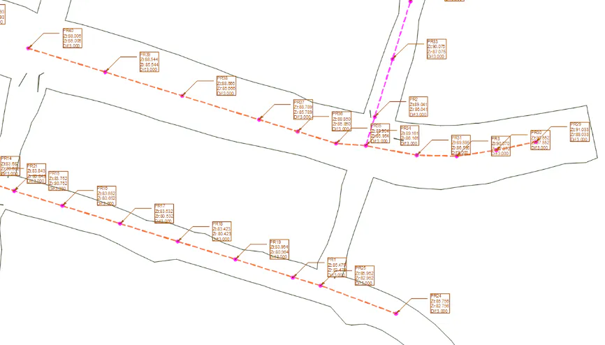
Now we run the Pipe Networks > Draw Pipes command, create two piping sections, one for the upper polyline and the other for the lower one. The command will ask us for the nodes, and we indicate them from right to left.
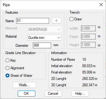
Once the nodes have been designated, press ESC and the following dialogue box will appear in the upper section, which we validate in accordance with their data.
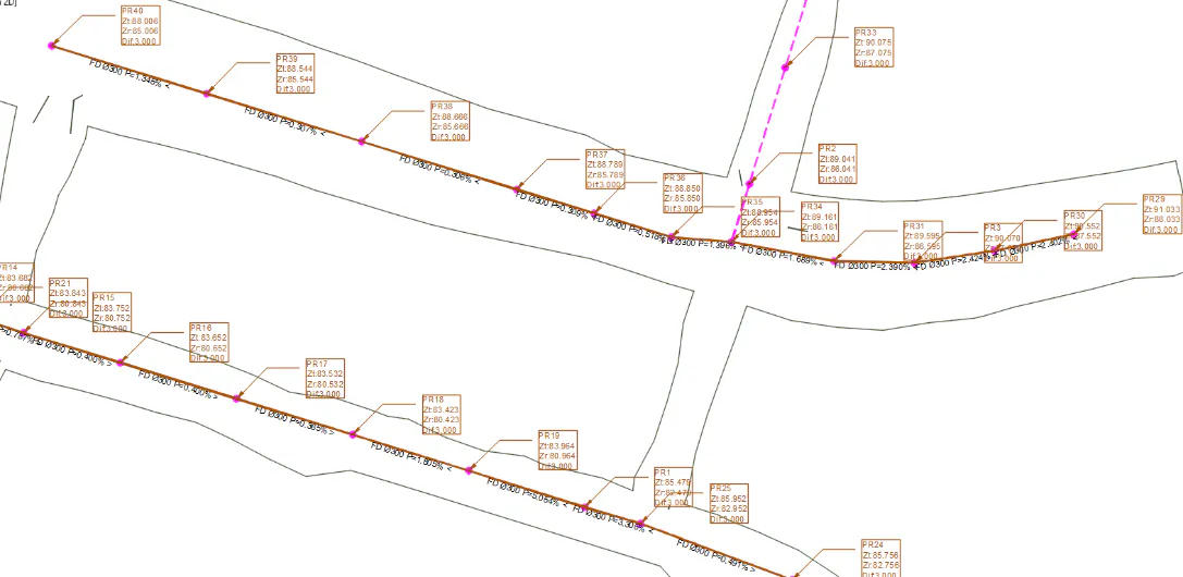
We also execute the same for the lower pipe section. The end result is illustrated in the screenshot below:
Moreover, we are going to proceed with the rainwater network, and in this case, we are going to create the pipes defined from north to south and with polylines in blue. We will define two pipes, designating the nodes from north to south and using same command as in the previous step, Draw pipes.
We will accept the values as they appear by default in the definition of the section. The end result is illustrated in the screenshot below: