
tcp PointCloud Editor
Extrude entities - PCE
13.22 Extrude Entities
Location
- Ribbon menu
- CAD Drawing
- EDIT 3D
- Geometry
- Extrude (Clear Entities)
- Geometry
- EDIT 3D
Description
This command extrudes the selected entities. The result will be a new set of 3d polylines, and 3d lines or faces.
The extrusion can be done in one direction or against a reference plane.
Parameters
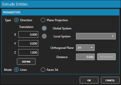
| Name | Meaning |
|---|---|
| Type | May be Direction or Plane Projection |
| X | X-component of the direction vector. Applies when Type Direction is checked |
| Y | Y-component of the direction vector. Applies when Type Direction is checked |
| Z | Z-component of the direction vector. Applies when Type Direction is checked |
| Global System | Use global system orthogonal plane. Applies when Type Direction is checked |
| Local System | Use local system orthogonal plane. Applies when Type Direction is checked |
| Orthogonal Plane | The orthogonal plane to use in the global or local system |
| Mode | May be Lines or Faces 3d. Type of entity to be used in the extrusion |
How to use
-
Select a set of entities.
-
Start the Extrude Entities command.
-
Set the type to "Direction" or "Plane Projection"
-
Depending on the type of extrusion selected:
-
If the selected type is "Direction", define the direction vector by assigning values to the X, Y and Z parameters.
-
If the selected type is "Plane Projection", set the System and Orthogonal Plane in that system.
-
-
Set the mode to "Lines" or "Faces 3d".
-
Click OK button to accept the creation of the new entities or CANCEL button to cancel the command.