
tcpMDT
[PRO] edit nodes - MDT25
14.5 [PRO] Edit Nodes

This tool enables us to edit the node and change its characteristics. When executing the initial command, we will be asked whether the node to be edited is drawn in top view mode or front view mode. Once the type of node to be edited has been specified, we select the node.
Editing nodes in top view mode
The following window will appear when selecting any node in top view mode.
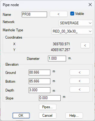
Name: The name of the node to be edited.
Visible: This option is enabled by default, in the case of deactivating it, the node will not be drawn either in plan or in elevation, when the elevation representation of the network is made.
This option is interesting when there is a vertex in the section due to a change of direction but a node is not really located at that point.
If we later want to edit the node once it has been set to not visible, we can select the block that is drawn associated with the node, which is not hidden.
Network: The network in which the node is located. The option of changing it.
Manhole Type: The block with which the node will be represented in the ground drawing.
Coordinates: The coordinates of the node with the option of specifying new coordinates.
Elevation:
-
Ground: The elevation of the node ground.
-
Grade line: The elevation of the node grade line.
-
Depth: The depth of the node. The difference between the ground elevation and the grade line elevation is the result of the depth. A change in the value of the depth will result in a change in the grade line elevation.
-
Slope: When you pass a stretch through the node, you can set the slice to enter one dimension and exit the node to a lower dimension. In this case the highlight indicates the output dimension, if its value is nonzero, the output dimension would be the dimension of the section minus the value of the highlight.
-
Pipes: Pressing this button displays the step of the different sections through the edited node. With the possibility of changing it.
Clicking on OK will update the node in accordance with the information provided.
Editing nodes in front view mode
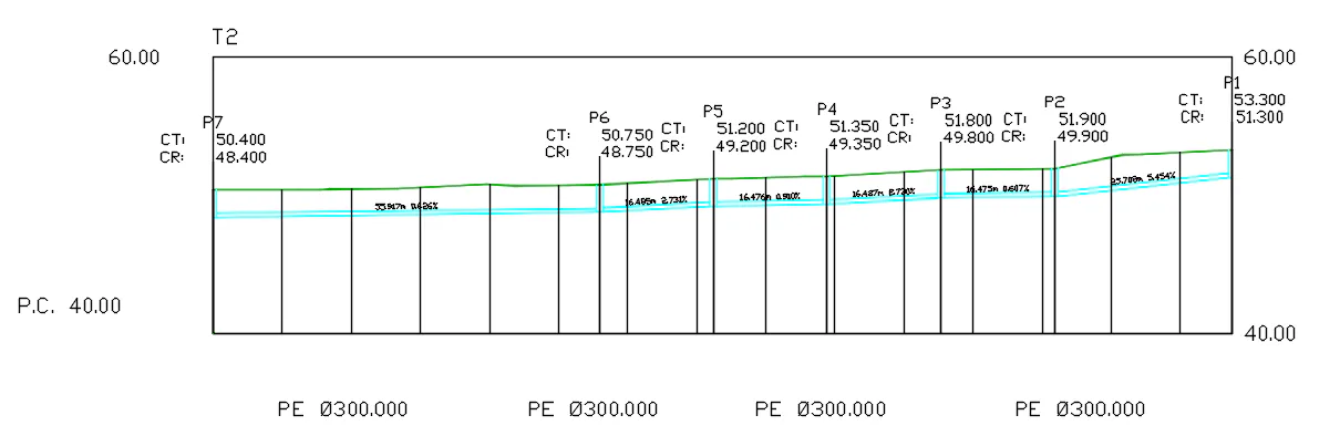
On selecting any of the nodes drawn in front view mode, we also have the option of editing the characteristics of the node, in addition to other properties that cannot be edited in front view mode, such as the drop shaft.
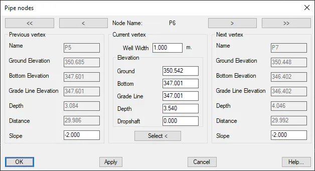
The upper buttons enable us to move to the initial vertex, previous vertex, next vertex and last vertex respectively.
Previous Vertex: Displays all the information on the node before the one we have selected. This includes the option to change the slope. The change in the value of the slope of the previous vertex implies a change in the grade line elevation of the current vertex and consequently in the depth of the same.
Current Vertex:
-
Well Width: The width of the well of the current vertex in meters.
-
Ground Elevation: The elevation of the ground of the current vertex. This value is normally the same as the value of the elevation of the surface at that point.
-
Grade Line Elevation: The grade line elevation of the current node.
-
Depth: The depth of the current node. A change in this value will result in a change in the grade line elevation of the current node.
-
Drop shaft: Each node features the option of assigning it an additional drop shaft or depth, which is useful for connection with other sections or for keeping slopes at certain values.
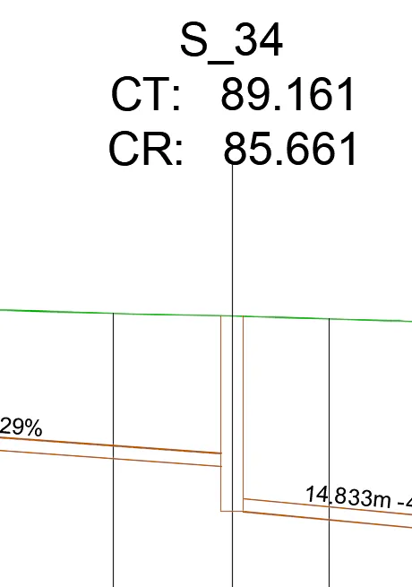
- Select: The option of designating a new node position on the longitudinal profile drawn.
Next Vertex: As in the case of previous vertex, the characteristics of this vertex include the option of changing the output slope from the current vertex.
Once the window has been checked, both the elevation information on the longitudinal profile and the drawing in top view mode will be updated, for both the edited node and the piping sections in question.