
tcpMDT
Local Systems. Introduction - MDT26
Introduction
Based on traditional coordinate transformation methods and according to their dimension, a classification has been made which includes these methods in addition to a combination of some of them.
3 groups of coordinate transformations are presented:
2D: 2-dimensional transformations among which the traditional methods of Helmert, Affine and Projective are distinguished plus a simple translation of X and Y coordinates.
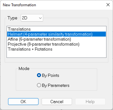
3D: 3-dimensional transformations including translations in X, Y, Z and the classical 7 parameter Helmert.
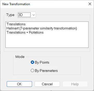
2D + 1D: 3-dimensional transformations using 4-parameter Helmert 2D for X, Y plus translation in Z or translation in Z and slopes X and Y.
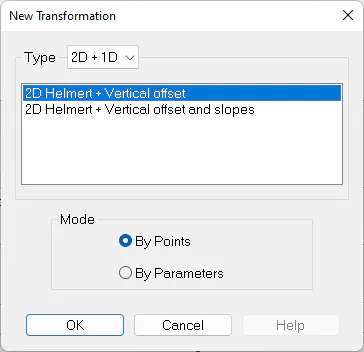
The operation is similar for each of the methods, two modes being distinguished to define the transformation:
By Points: Entering a series of pairs of source and target coordinates, in 2D or 3D, and calculating the equation system of the method selected.
By Parameters: Entering the values of the transformation equation parameters directly.
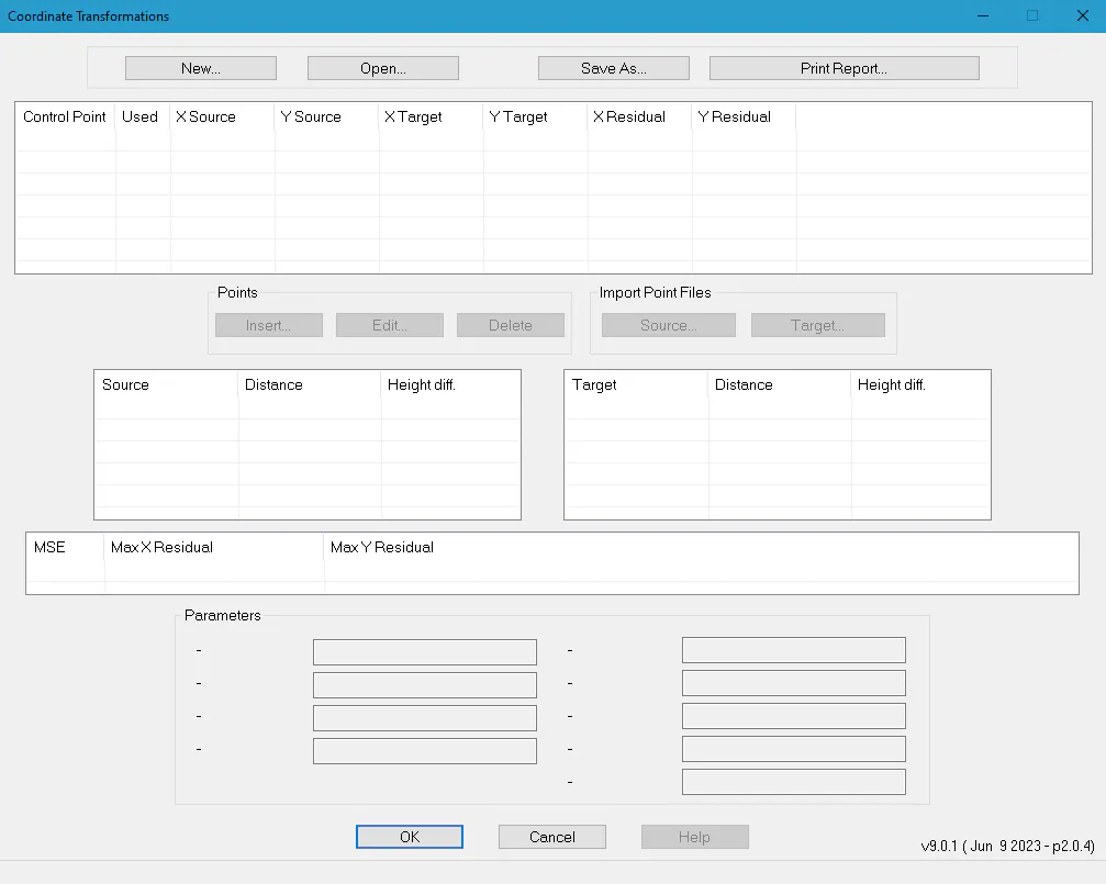
To create a new transformation, you must click the button New.... Similarly, you can load an already existing one by clicking the option Open.
Coordinate Transformation by Points
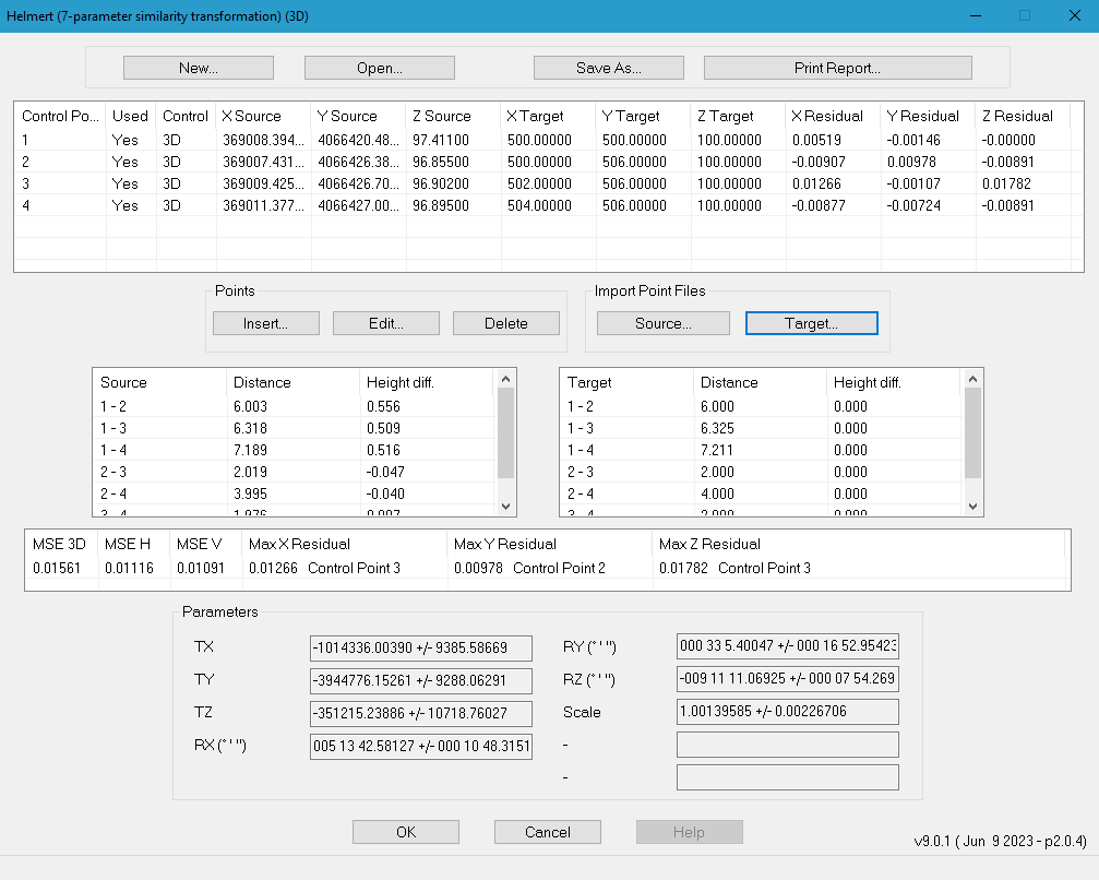
If the transformation is By Points, a list will be displayed at the top of the window with the following information:
Control Point: Number or name of the pair of points.
Used: You indicate with Yes or No whether the pair of points is involved in the transformation calculations. You can change its state by double-clicking on the desired line.
Control: For 3D and 2D+1D transformations, you indicate with 3D, H or V whether the pair of points is involved in the transformation with its X, Y and Z coordinates, with X and Y only, or with Z only, respectively. The default value for each pair will be 3D. To change this, you have to select the control point, click the Edit... button and activate/deactivate the H Control and V Control boxes.
X Source, Y Source, Z Source: X, Y, Z coordinates of the source point of the pair. Only X and Y are displayed for 2D transformations.
X Target, Y Target, Z Target: X, Y, Z coordinates of the target point of the pair. Only X and Y are displayed for 2D transformations.
Residual X, Residual Y, Residual Z: Differences in X, Y, Z between the actual values and the calculated values. Only X and Y are displayed for 2D transformations.
Points can be inserted manually or by importing files.
The Insert... button allows you to do so manually and displays the following window:
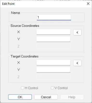
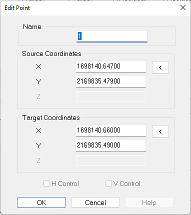
In this window you have to establish the name of the pair, the X, Y, Z coordinates of the source and target points and the H and V control.
The control and Z components will be displayed disabled for 2D transformations.
The < buttons allow you to select the coordinates from the CAD.
To insert the coordinates from a file you have to use the Source... and Target... buttons from the section Import Point Files. The points on the list which have the same identifier as the imported ones will be replaced.
Files can have any extension and must have the following line format:
NsepXsepYsepZ
The field separator, sep, can be a space, comma or tab and the Z component is optional.
Also, the program shows two lists of distances and height differences. They are created using pairs of source points and pairs of target points.

Transformation Results
The program attempts to resolve the equation system of the selected transformation every time any change is made to the list of pairs of points, whether this be inserting, editing or deleting pairs. If a solution is found, the calculated values will be displayed as well as the standard deviation of each parameter. The format of angles is sexagesimal, in degrees, minutes and seconds, and anti-clockwise with 0 in the East.
At the same time, the mean square error and maximum residues of each X, Y, Z component are also presented.
Depending on the dimension of the transformation, the following mean square errors are calculated:
2D : Mean square error H (X, Y).
3D : Mean square error 3D (X, Y, Z), H (X, Y), V (Z).
2D + 1D : Mean square error H (X, Y), V (Z).
Coordinate Transformation by Parameters
In addition to transformations by points, it is possible to create coordinate transformations by manually entering the equation parameters.
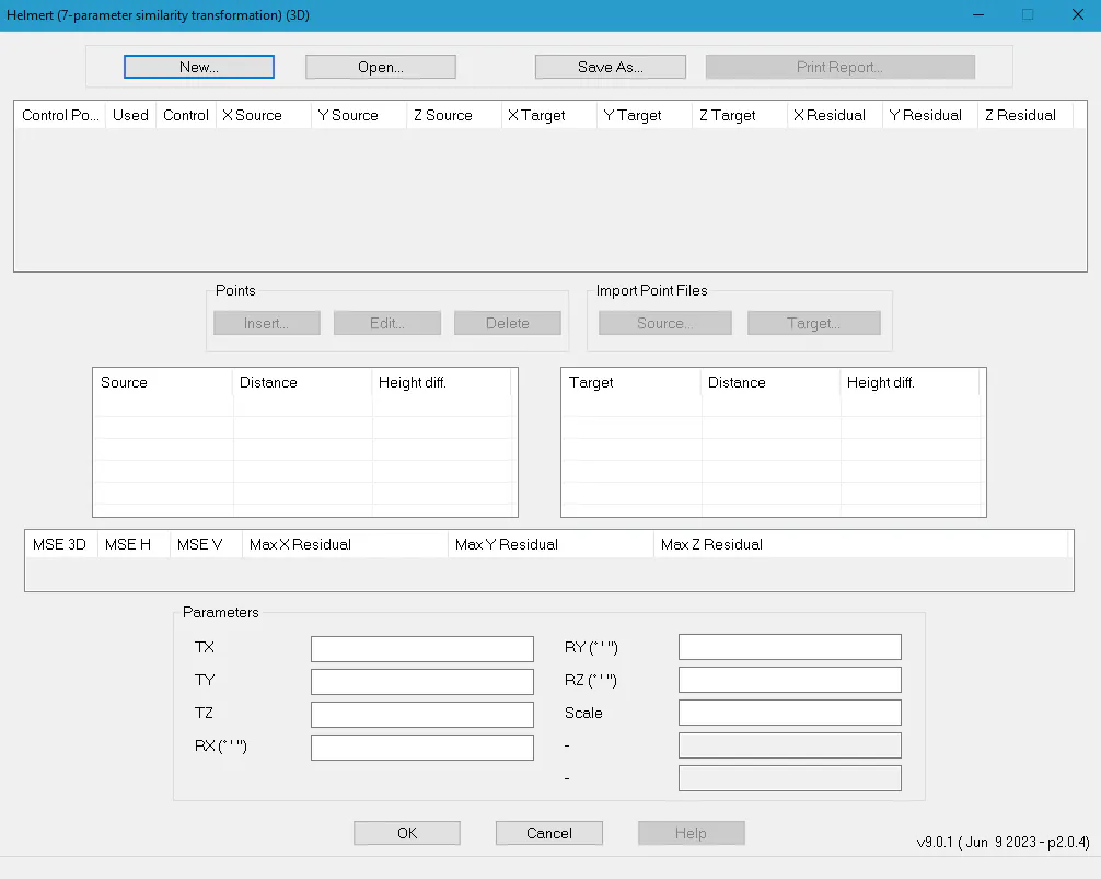
Depending on the type of transformation selected, the corresponding boxes will be enabled in the Parameters section at the bottom of the window.
The format of the angles entered must be sexagesimal, in degrees, minutes and seconds, and anti-clockwise with 0 in the East.
Creation of Transformation Report and File
Once the coordinate transformation has been created, either by points or parameters, it can be saved using the Saved As... button.
This command will create an ASCII file with NTR extension and with the name indicated.
The following is an example of a Helmert 3D transformation:
[Type]
3D Helmert (7-parameter similarity transformation)
[Parameters]
10233.82581
6549.96829
720.87886
0.039864983450463
-0.009613724297046
-2.364273637689549
0.949956940242192
[Inverse Parameters]
12535.20274
-2626.33944
-379.86565
0.021685600857773
-0.034806842462851
2.364842746568201
1.052679285294726
[MSE]
3D 0.06841 H 0.06734 V 0.01204
[Inverse MSE]
3D 0.07202 H 0.07045 V 0.01495
[Standard Deviation]
0.06119
[Max X Residual]
0.04803 (Control Point 1)
[Max Y Residual]
0.08454 (Control Point 4)
[Max Z Residual]
0.01920 (Control Point 4)
[Control Points]
4
[Point Used HControl VControl XSource YSource ZSource XTarget YTarget ZTarget XRes YRes ZRes]
1 1 1 1 1094.88300 820.08500 109.82100 10037.81000 5262.09000 772.04000 0.04803 0.02520 -0.00113
2 1 1 1 503.89100 1598.69800 117.68500 10956.68000 5128.17000 783.00000 0.00796 -0.05610 0.01150
3 1 1 1 2349.34300 207.65800 151.38700 8780.08000 4840.29000 782.62000 -0.01395 -0.05365 0.00884
4 1 1 1 1395.32000 1348.85300 215.26100 10185.80000 4700.21000 851.32000 -0.04204 0.08454 -0.01920
For coordinate transformations by points, the button Print Report... lets you create a document of this type with all the transformation data.
Transformation Data
File D:\test1.htm
Type Helmert (7-parameter similarity transformation) (3D)
Date / Time 21/12/2015 11:43:46
Parameters
TX 10233.82581 ± 0.06721
TY 6549.96829 ± 0.06805
TZ 720.87886 ± 0.22878
RX 002°17\'2.74309\'\' ± 000°00\'30.33323\'\'
RY -000°33\'2.97298\'\' ± 000°00\'8.74588\'\'
RZ -135°27\'46.44379\'\' ± 000°00\'7.77431\'\'
Scale 0.94995694 ± 0.00003576
r11 -0.712764
r12 0.701339
r13 -0.009614
r21 -0.700541
r22 -0.712499
r23 -0.039853
r31 -0.034800
r32 -0.021671
r33 0.999159
Statistics
MSE 3D 0.06841
MSE H 0.06734
MSE V 0.01204
Standard Deviation 0.06119
Max X Residual 0.04803 (Control Point 1)
Max Y Residual 0.08454 (Control Point 4)
Max Z Residual 0.01920 (Control Point 4)
Control Points
Control Points Count 4
Control Point | Used | Control | X Source | Y Source | Z Source | X Target | Y Target | Z Target | X Res | Y Res | Z Res |
|---|---|---|---|---|---|---|---|---|---|---|---|
1 | Yes | 3D | 1094.883 | 820.085 | 109.821 | 10037.810 | 5262.090 | 772.040 | 0.04803 | 0.02520 | -0.00113 |
2 | Yes | 3D | 503.891 | 1598.698 | 117.685 | 10956.680 | 5128.170 | 783.000 | 0.00796 | -0.05610 | 0.01150 |
3 | Yes | 3D | 2349.343 | 207.658 | 151.387 | 8780.080 | 4840.290 | 782.620 | -0.01395 | -0.05365 | 0.00884 |
4 | Yes | 3D | 1395.320 | 1348.853 | 215.261 | 10185.800 | 4700.210 | 851.320 | -0.04204 | 0.08454 | -0.01920 |