tcpMDT
Creating cross sections - MDT26
2.7 Creating Cross-Sections
Now, we obtain the cross sections on this alignment. Thus, we execute the option Cross-sections> Create Cross-Sections (or Cross-section> Create > Create Cross-Sections) by selecting the drawing alignment.
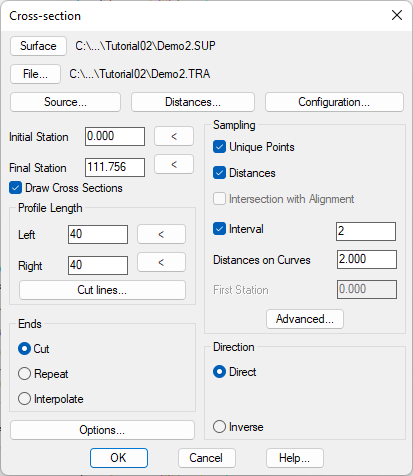
In the cross-section profiling dialog box, MDT proposes the DEMO2.SUP file as the surface, which is the current surface of the drawing, and proposes as cross section name the same alignment file name with TRA format. Finally, we move on to the bandwidth parametrics, entering 40.00 meters on the Left as well as on the Right, so that we section the entire model without omitting any areas. Check the Unique Points box. The Interval between profiles will be 2.00 meters; though normally excessive, it does not generate any problem in its execution. Finally, we check the Draw Cross Sections box, and once the profiles are generated, they will be drawn automatically.
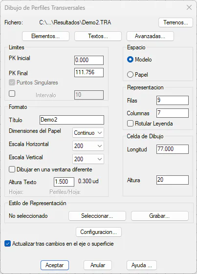
Press OK and a message will appear indicating that all the profiles have been generated correctly. The profiles will be drawn in plan with their respective cuts and finally a window will pop up before the drawing of cross sections. We will validate the drawing window with Space Model, Paper Size in Continuous, Horizontal Scale 200 and Vertical Scale 200. We will select the right part of the current drawing as the drawing origin.
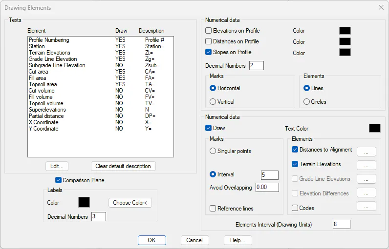
Additionally, we press the Elements button and configure the different options according to the following capture, the idea is to draw the comparison plane, the guitar and the slopes associated with each profile.
We will select the right part of the current drawing as the source of the drawing.
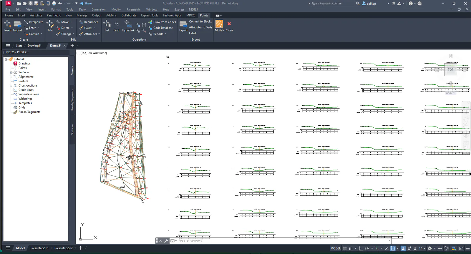
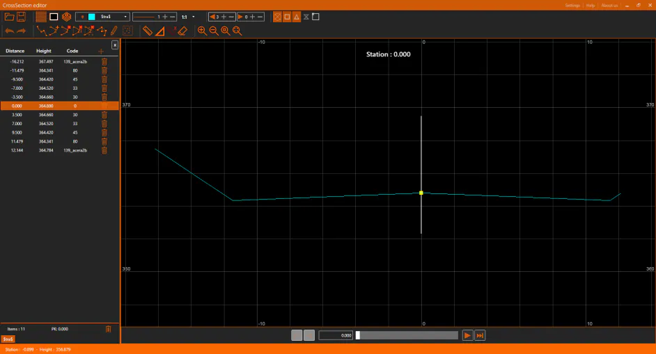
The program also allows us to graphically review these on-screen profiles in a quick one-to-one manner, in order to verify them, by indicating the represented station and the alignment position coordinate. The latter option is accessed through the Cross-Sections> Review Cross-Sections menu (or Cross-Sections > Edit> Check) or its equivalent in the project window.
We select DEMO2.TRA in the window that shows us the cross section list of the project. Then, the program will display the drawing of the cross sections on an alignment and centered. We can move forward and backward within the cross sections by pressing the Next and Previous buttons, respectively.