tcpMDT
Generating contour lines - MDT26
2.4 Generating Contour Lines
We complete the DTM process and start with the contour lines, which possibly suggests some new edition of the triangulation, in order to have the greatest resemblance to the known terrain morphology.
We select the option Contour Lines/Mapping > Create Contour Lines (or Contour Lines > Drawing > Contour Lines) or Draw Contours option from the context menu of the project window, by having selected the Demo2.sup surface.
The drawing scale and the comprehensive definition of taken and added points, makes the representation with 0.5 m. of normal equidistance. So we modify the Minor box by overwriting this field with 0.500. Bear in mind that the validation of the data automatically modifies the equidistance value of the master contours to 2.500 (= 0.500 x 5).
We establish the smoothing factor of the contours at 0, by unchecking the Smoothing factor option, as it is advisable not to smooth them initially so as not to overload the drawing.
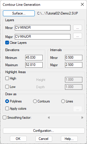
Press OK to start the process.
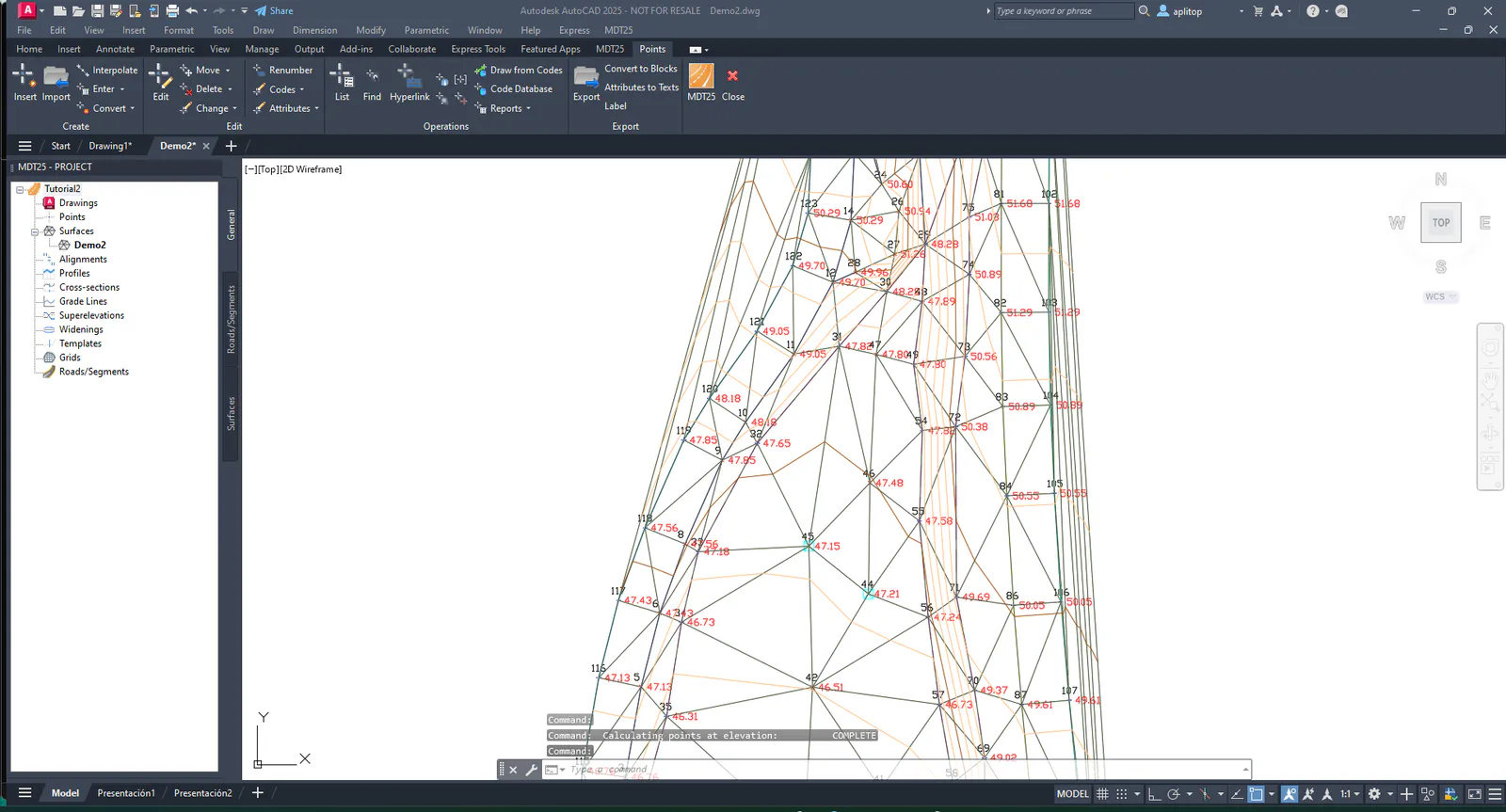
Then, we review the modeling effects in detail through their representation of contour lines. Expand the surroundings of point 27 with the command Points > Find Point (or Points > Operations > Find).
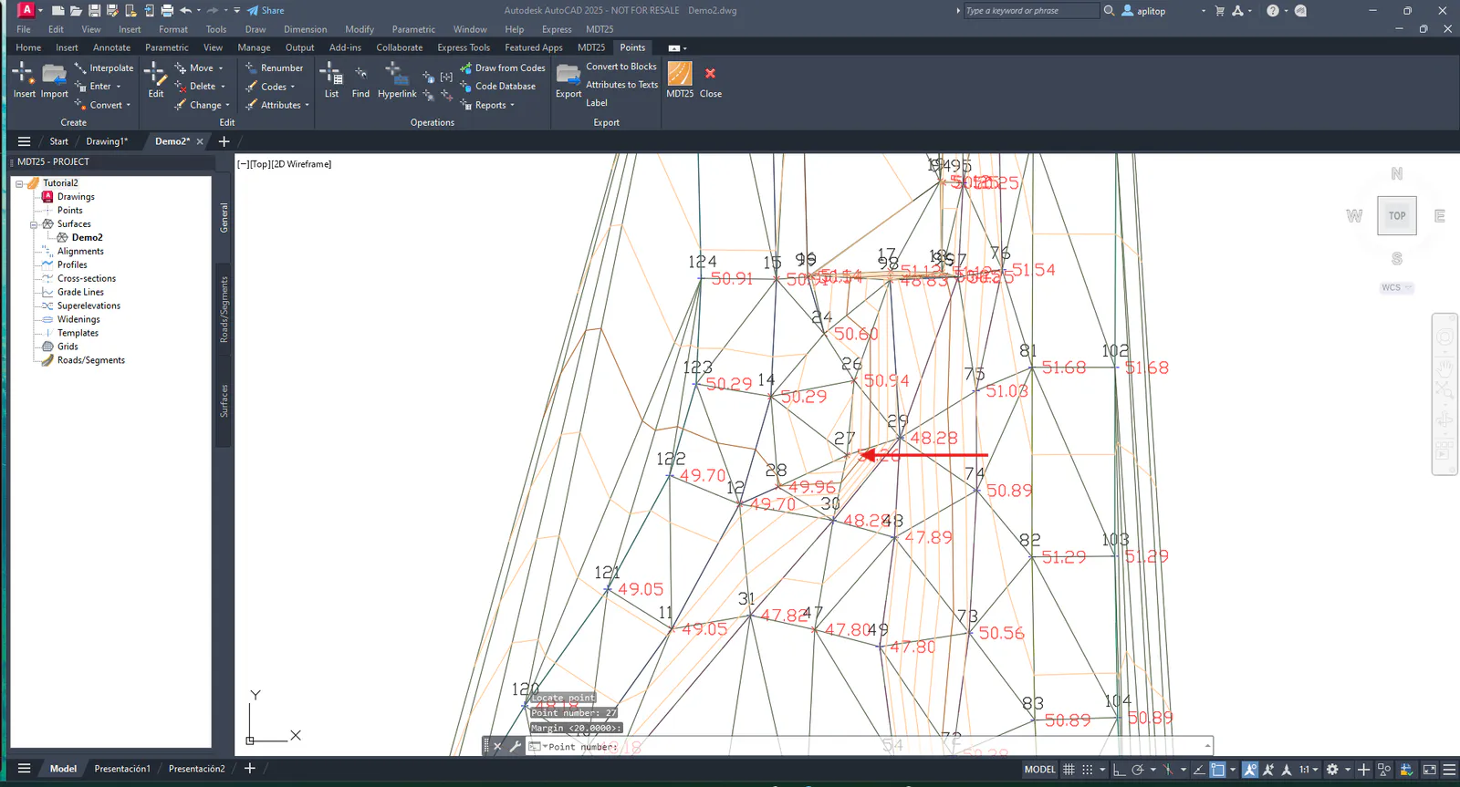
We see that the contour-laying under point 27 curls in the direction of point 48 and we avoid the contour rate between 30 and 47. We can correct it by inserting a triangulation line between point 31 and point 48. Hence, execute the command Surfaces > Insert Line (or the Surfaces > Edit > Insert Line option), and join points 31 and 48. Please, observe that both triangulation and contour change instantly.