
tcpMDT
Tour by road - MDT26
11.4 Tour by Road
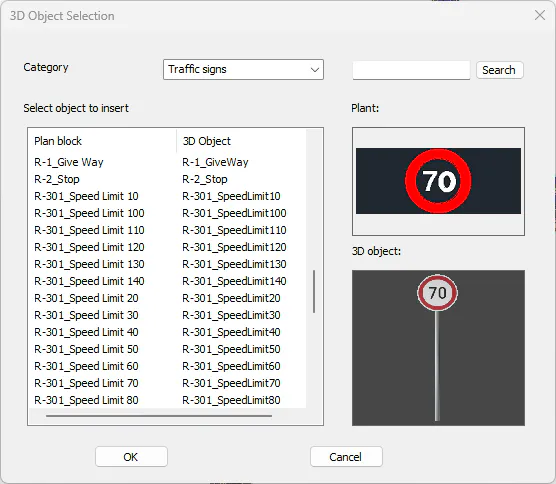
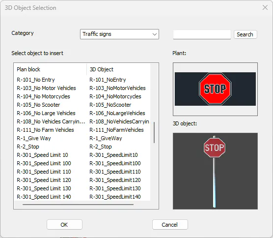
Before making the 3d tour of the road, we are going to insert vertical signage, to do this, we execute the option Maps > Insert 3D Objects, the following window will appear in which we will select the vertical signage to insert.
As a first signal, we are going to insert a limitation of 70 km/h.
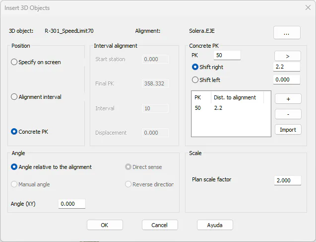
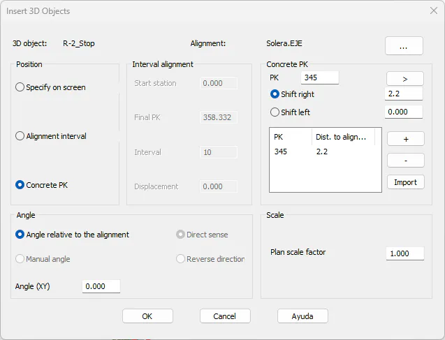
Once selected, the following window will appear in which we will establish the situation of it on the drawing.
With the (...) button we select the axis from the drawing or from the file by selecting solera.eje.
We activate the "Concrete PK" option and indicate Pk 50 at 2.2 meters to the right.
In the same way, we are going to insert two more signals:
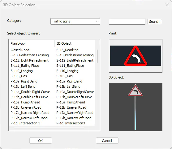
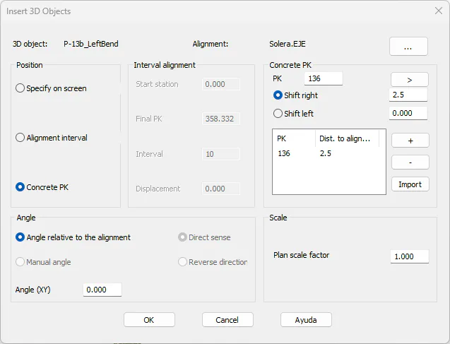
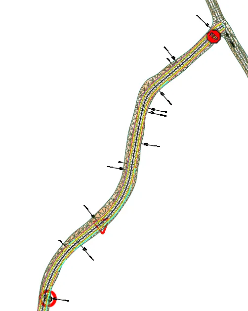
The result should look like the following image, in which you can visualize the three inserted signals:
Finaly we run the command Maps > Route by Road (or Maps > Viewer > Route by Road), press the Segment button and select the solera.SEG file. Then press the Surface button and select the solera.SUP file.
We configure the simulation parameters according to the attached window.
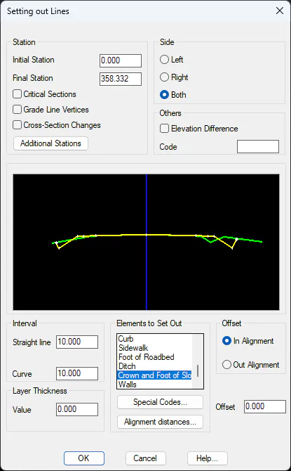
Before carrying out the simulation we are going to add some linear objects on the outer shoulder on both sides, to do this, we press the Insert Linear Objects button and the following window will appear.
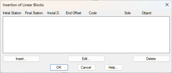
We hit the Insert button and create a new linear object according to the settings you can see below.
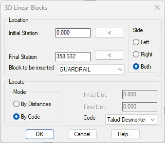 | 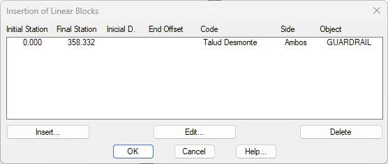 |
|---|---|
Once the linear objects have been inserted, we press the Accept button in the Route by Road dialog and a window with the realistic representation of it will be displayed.
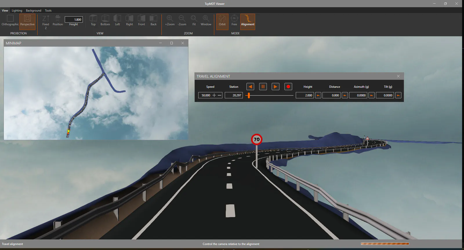
File Overview
Once the job is finished, we list the existing project files in the C:\MDT25_Projects\Tutorial11 directory. The main files are the following
File Description
solera.dwg Drawing with the original ground
solera.SEG Road segment file
solera2.SUP Proposed surface file
solera.EJE Horizontal alignment file