
tcpTunnel CAD
CAD viewer - TNC3
12.6 CAD Viewer
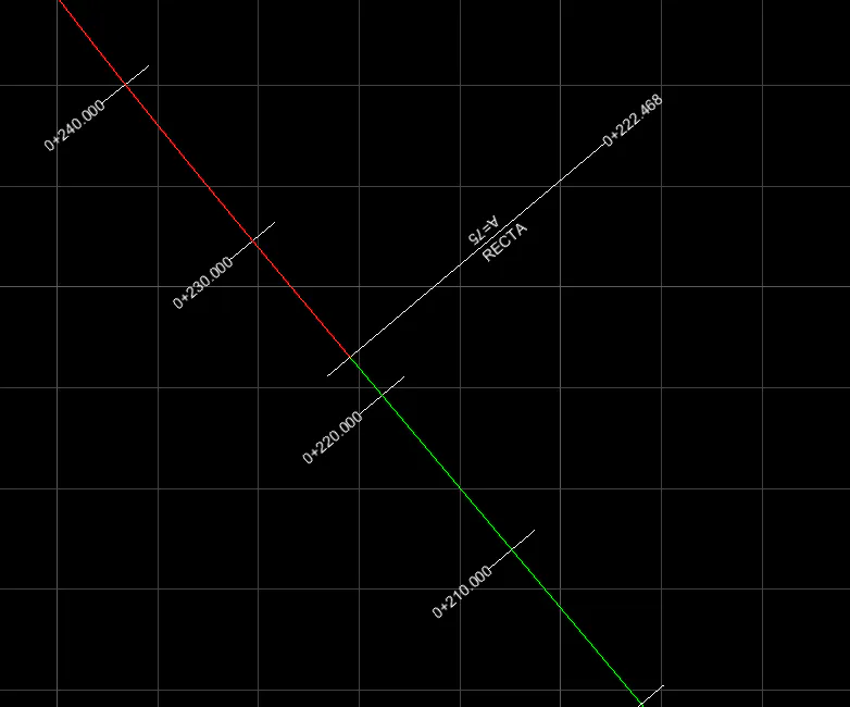
In the CAD viewer, the axis is drawn as a series of polylines, one per segment, along with its annotations. Each type of alignment is represented by a color, which can be adjusted by modifying the layer colors or, permanently, in the application Settings.
If a segment of the axis is clicked, it will be highlighted graphically in the CAD viewer and in the axis panel. When selected, the segment is displayed as a dashed line with greater thickness, the polyline vertices of the segment are shown, and the polyline color is inverted.
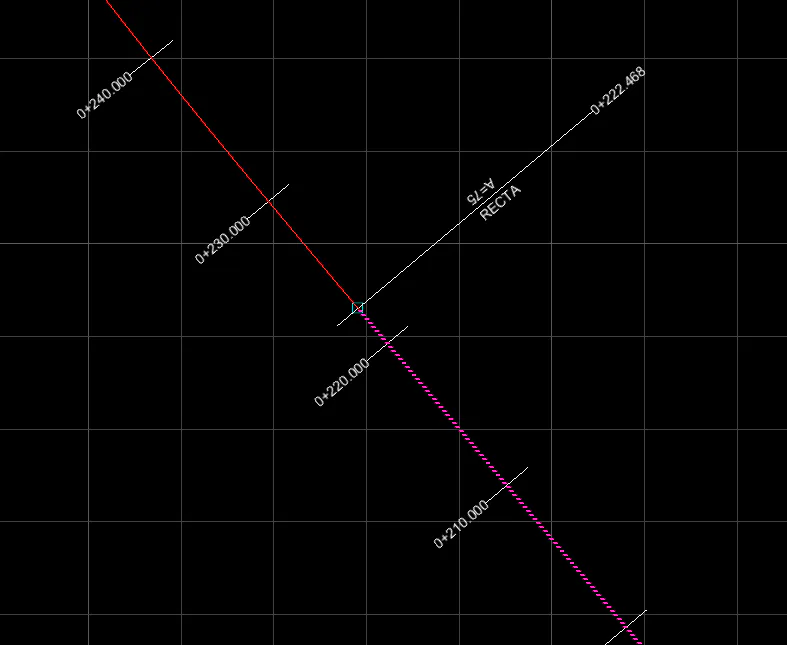
At this point, if the cursor is placed over one of the vertices it will be highlighted and the radial context menu will appear.
Radial Context Menu
When the cursor is placed over a vertex of a polyline of a selected axis segment, the radial menu appears with the available editing options:
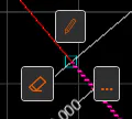
Edit: Displays the Edit Axis Node dialog for the selected segment.
Delete: Removes the segment. It can also be deleted, once highlighted, by pressing the Delete key.
More options: Shows the context menu.
Context Menu
At any time when right-clicking on the CAD viewer, the application context menu appears:
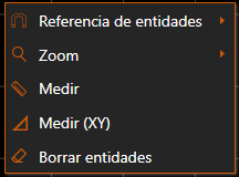
The measurement and entity deletion operations are the same as in the Measurement and Delete Menu of the toolbar.
Likewise, in the Entity Reference and Zoom submenus, the commands from the menus of the same name in the toolbar are found.
If the application is in a command and the context menu is opened by right-clicking in the CAD viewer, additional options will be given to end the command via Enter or Escape.