
tcpMDT
[PRO] set out alignment points - MDT25
16.10 [PRO] Set-out Alignment Points

This tool facilitates the task of obtaining the coordinates of points belonging to the horizontal alignment. It also has an optional offset. The program first requests the horizontal alignment file (by default, the name of the current drawing with an .EJE extension) to be selected. Alternatively, one can also select a segment, in which the elevation of the grade line in the segment (see Definition of Segment) must also be entered. The dialog box and a description of its characteristics appear below.
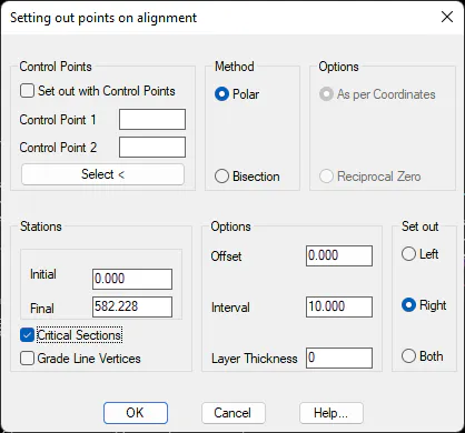
Control Points: Setting out stations that will be used to perform the calculation. Control Point 1 represents the positioning control point and Control Point 2 represents the reference control point. Their names can either be keyed in or selected on screen.
Method: Types of setting out methods that can be used, either Polar or Bisection. The bisection method has different options: Reciprocal Zero and As per Coordinates.
Initial station: Initial station from which the setting out will be performed.
Final station: Final station up to which the setting out will be performed.
Critical Sections: If it is enabled, the horizontal alignment's critical sections will also be set out.
Grade Line Vertices: If it is enabled, the grade line vertices will also be set out.
Options
Offset: Offset to the horizontal alignment of the points to be set out, also called setting back. If it is negative, it is to the left of the horizontal alignment; and if it is positive, it is to the right of the horizontal alignment.
Interval: Station intervals at which the setting out is to be performed.
Thickness: This value will be considered if a segment is selected, in which case the value entered in this box will be subtracted from the resulting grade line elevation. The value should always be positive.
Set Out: The horizontal alignment side one wishes to set out is entered in this box. Left, *Right or Both*.
Once the dialog box has been validated, the different lists, depending on the method selected, will appear as follows.
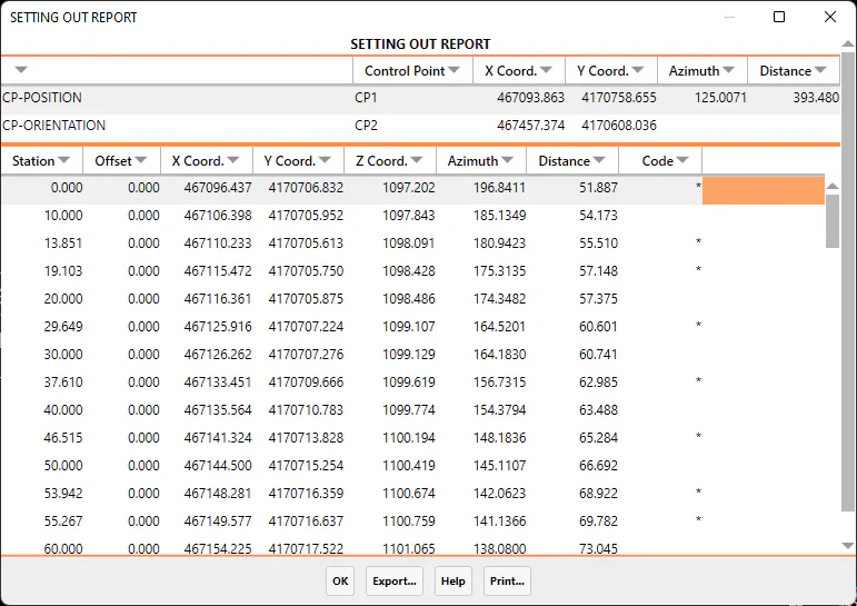
Setting Out by Polar Method
For each interval from the initial station to the final station, it displays the station, offset, X, Y and Z coordinates, azimuth and distance from the control point, and code. The latter will be an asterisk (*) for critical sections. The Z Coordinate is obtained from the segment file, should it be defined.
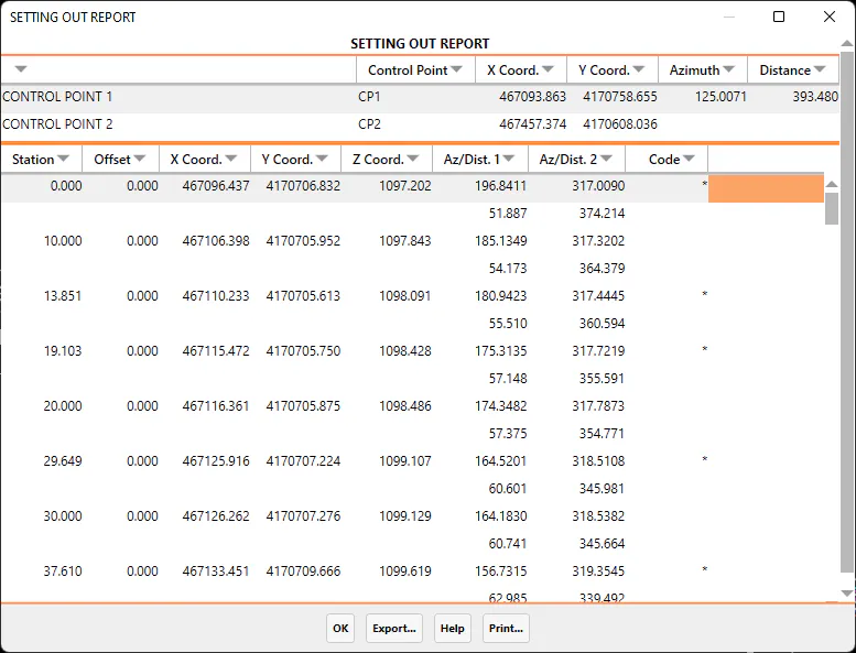
Setting out by Bisection Method
For each interval from the initial station to the final station, it displays the station, offset, X, Y and Z coordinates, azimuth and distance from the base and reference control points, and code. The latter will be an asterisk (*) for critical sections. The Z Coordinate is obtained from the segment, should it be defined.
The possibility exists for all the different lists of exporting and printing the data obtained. A description of each of the options follows:
Export
When the Export option is selected, the program displays a new dialog box with different ways of exporting the data. The dialog box and a description of its characteristics appear below:
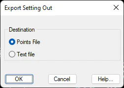
Points file: All the coordinates of all the points on the list are exported to a points file. When the dialog box is validated, the Export Points command is automatically executed. For further details, see the Points section.
Text file: Sends the contents of the list to an ASCII file, so that it can be edited or handled with a word processor.