
tcpMDT
[PRO] set out polylines with respect to an alignment - MDT25
16.12 [PRO] Set-out Polylines with Respect to an Alignment

This tool will be of great use if one wishes to set out a set of polylines with regard to a horizontal alignment or segment without the need of creating points on such polylines.
Once the command is executed, the program requests the horizontal alignment or segment. Should a segment be selected, the program provides information on the elevation of the point set out on the definitive road in the setting out list.
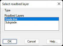
If the segment is selected and it has an associated section, the command asks for which layer of roadbed the elevation must be analyzed.
Once the horizontal alignment or segment is selected select the polyline for setting out. Lastly, the following dialog box is displayed, where the kind of setting out one wishes to perform is configured.
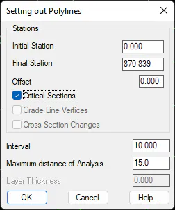
Initial station: Initial station from which the setting out will be calculated.
Final station: Last station up to which the setting out list will be created.
Offset: Additionally, a displacement may be specified with regard to the designated polylines, meaning, it is as if it were really analyzing parallels to the selected polylines keeping the sign in mind (negative > Left -- Positive > Right).
Critical Sections. If enabled, the alignment's critical sections are also displayed on the report.
Grade Line Vertices: In this case, the grade line's transition curves vertices are also added.
Cross-Sections Changes: All the stations at which some assignment changes regarding the template associated to the segment has been done are added to the list. This option is only valid should one be working with Segments.
Interval: Value indicating the interval with which the setting out is to be performed.
Layer Thickness: In the event of setting out a segment, the program can apply a layer thickness to the final elevation calculated. This value is always positive and is subtracted from the definitive elevation.
Once the dialog box has been validated, MDT performs a calculation with the aforementioned data and displays a list with the following information on each line: station and offset from vertex selected with regard to horizontal alignment, X, Y and Z coordinates, and the code corresponding to the vertex set out.
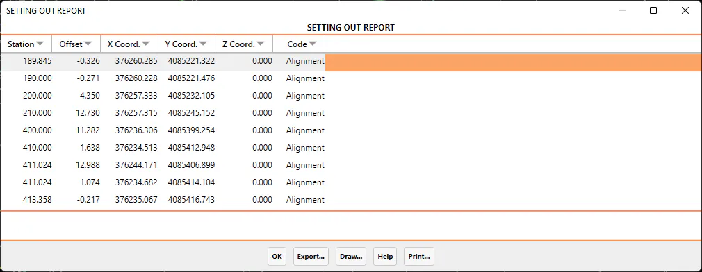
The possibility of exporting, printing or drawing points from the data obtained exist in the final list. A description of each of the options follows:
Export
When the Export option is selected, the program displays a new dialog box with different ways of exporting the data. The dialog box and a description of its characteristics appear below:
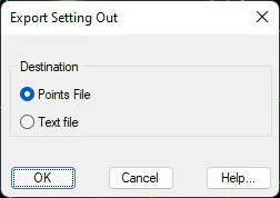
Points file: All the coordinates of all the points on the list are exported to a points file. When the dialog box is validated, the Export Points command is automatically executed. For further details, see the Points section.
Text file: Sends the contents of the list to an ASCII file, so that it can be edited or handled with a word processor.
When this option is selected, the data listed is sent to the printer selected.