
tcpMDT
Elements. Introduction - MDT26
Introduction
MDT incorporates new functionalities for the Road Layout, especially in terms of alignment integration and design. The program encompasses the concepts of fixed, coupled, revolving, mobile and link alignments.
Fixed Alignment
A fixed alignment includes all the parameters required to determine its position. It is defined by means of two points and a radius (0 for straight segments). Furthermore, it may include a setback distance and two clothoids (for output and output at the fixed segment).
Three points may also be used to define a fixed circular. The program deduces the radius and thereafter assumes that two points and a radius have been used.
Coupled Alignment
A coupled alignment is supported on an alignment already calculated to determine its position. At the final or initial point of the already calculated alignment, and with the corresponding azimuth, the layout elements of the coupled alignment concatenate.
It is defined by its radius, its length and the parameters of the input and output clothoids. Furthermore, it has a final item of data pertaining to the length (or an increase in length) of the alignment on which it is supported. In view of this latter data, and bearing in mind whether the alignment calculated is the previous or subsequent one, four subtypes can be distinguished between
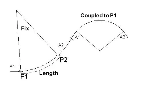
Coupled to P1
The coupled alignment replaces the length calculated on the previous alignment. For the new final point, the coupled alignment is concatenated.
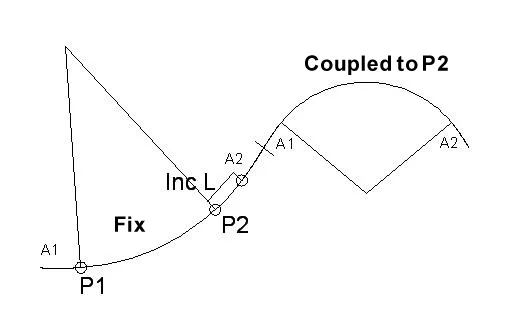
Coupled to P2
The coupled alignment extends the length calculated on the previous alignment. For the new final point, the coupled alignment is concatenated.
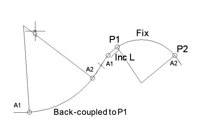
Back-coupled to P1
The coupled alignment extends the length calculated on the subsequent alignment. Before the next alignment, the layout elements of the coupled alignment are inserted.
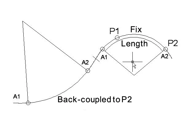
Back-coupled to P2
The coupled alignment replaces the length calculated on the subsequent alignment. Before the next alignment, the layout elements of the coupled alignment are inserted.
Revolving Alignment
A revolving alignment is also supported on a calculated alignment and it meets the condition that it passes via a fixed point of known coordinates or at a distance from the latter. To achieve this, it modifies the length of the fixed alignment and calculates the length of the revolving alignment.
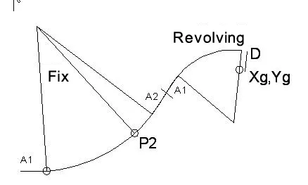
Two types are distinguished between, Revolving and Back-revolving, depending on whether it is supported on the previous or subsequent alignment. The data it includes are the radius, the clothoid parameters, the crossing point, and optionally a distance to the crossing point.
Mobile Alignment
A mobile alignment is defined by its radius and the parameters of the input and output clothoids. In order to calculate it, the previous and subsequent alignment are calculated.
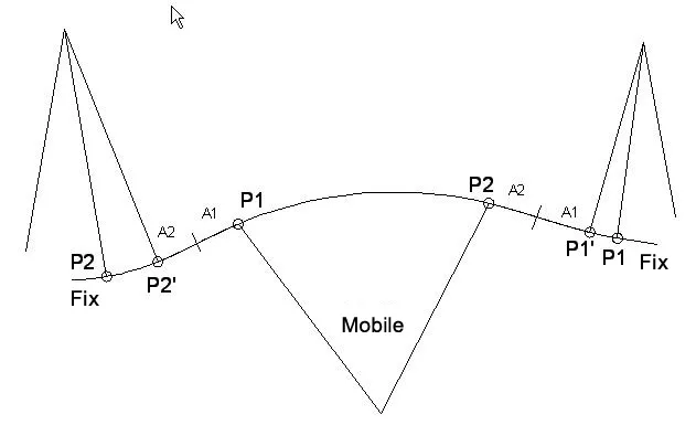
During the calculation process the lengths of the previous and subsequent alignments are modified in such a way that that the elements are tangential to each other.
There are cases in which two mobile alignment solutions are possible. In this case, the program opts for the shortest development solution. To use the other solution, the type has to be changed to Special Mobile.