tcpMDT
Marks - MDT26
Marks
To use the following commands, it is important to ascertain the following concepts:
Marks: this is the name given to those blocks inserted with the command Create Marks and they are used to indicate the support points in an image.
Links: this is the name given to the line which joins a Mark to an MDT Point by means of the command Create links of marks to points and they will be used to pair the support points of the images with the field points when Georeferencing or Deforming an image.
Reference lines: the concept is similar to that of the Link, but simpler as it does not require Marks or MDT Points, only designating on the screen an origin and a destination. They are created with the command Create reference lines.
Using Links or Reference lines will depend on the user's likes and requirements, but both may be used either together or separately to calculate the Georeference or Deformation of an image.
Split into Two Window
 | Command to execute in the CAD |
|---|---|
Vertical menu | MDT26 > Images > Marks > Split into Two Windows |
Ribbon menu | Image > Marks > Split Window |
Command line |
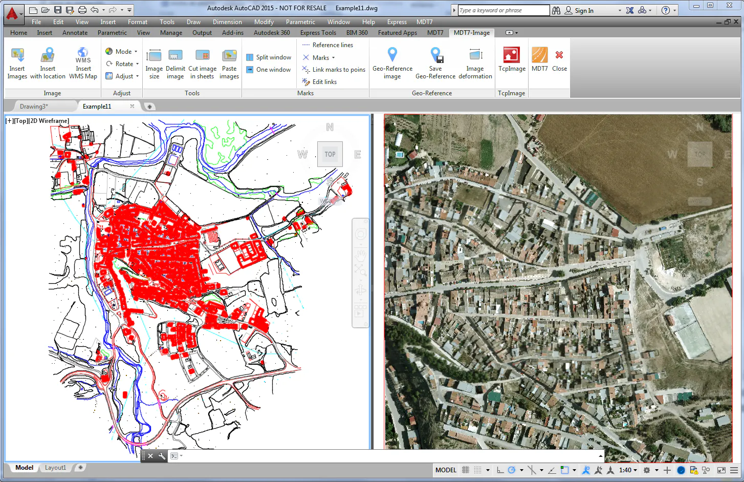
This command allows the division of the work space into two windows to delimit the first window will request the selection of an image and for the second window two points and in this way on the first window we will have a zoom extension over the image and in the second window a zoom extension over the selected area. This command will facilitate the drawing of Reference lines for us and the creation of Marks and Links.
Restore Single Window Mode
| Command to execute in the CAD |
|---|---|
Vertical menu | MDT26 > Images > Marks > Restore Single Window Mode |
Ribbon menu | Image > Marks > Single Window |
Command line |
This command allows the workspace to be restored to a single window.
Create Reference Lines
| Command to execute in the CAD |
|---|---|
Vertical menu | MDT26 > Images > Marks > Create Reference Lines |
Ribbon menu | Image > Marks > Reference Lines |
Command line |
This command allows the creation of Reference lines which will be used for the Georeferencing or Deformation of images. All the Reference lines will be drawn on the same "IMG-REFERENCE" layer and in one color by defect, both the name of the layer as well as the color of the line may be modified under Utilities > Configuration > Images. The command will request an origin which will be the points on the image and a destination corresponding to field points.
Create Marks
| Command to execute in the CAD |
|---|---|
Vertical menu | MDT26 > Images > Marks > Create Marks |
Ribbon menu | Image > Marks > Create Marks |
Command line |
This command allows the creation of Marks to indicate support points on an image and which will subsequently be used as an origin in the creation of Links for the Georeferencing or Deformation of images. All the Marks will be drawn on the same "IMG-MARKS" layer and in a default color and both the name of the layer as well as the color of the line can be changed under Utilities > Configuration > Images.
Move Marks
| Command to execute in the CAD |
|---|---|
Vertical menu | MDT26 > Images > Marks > Move Marks |
Ribbon menu | Image > Marks > Move Marks |
Command line |
This command allows the selected Mark to change position.
Delete Marks
| Command to execute in the CAD |
|---|---|
Vertical menu | |
Ribbon menu | |
Command line |
This command allows the selected Mark to be deleted.
Link from Marks to Points
| Command to execute in the CAD |
|---|---|
Vertical menu | MDT26 > Images > Marks > Link from Marks to Points |
Ribbon menu | Image > Marks > Create Link |
Command line |
This command allows a Link to be created, selecting a Mark as an origin and an MDT Point as a destination, thereby identifying a pair of points which will subsequently be used for the Georeferencing or Deformation of an image.
Edit Links
| Command to execute in the CAD |
|---|---|
Vertical menu | MDT26 > Images > Marks > Edit Links |
Ribbon menu | Image > Marks > Edit Links |
Command line |
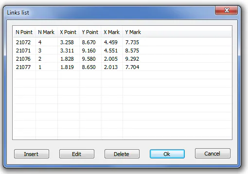
This command shows a dialogue in which the links created can be inserted, edited and deleted.
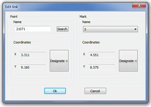
When selecting an element from the list and pressing Insert or Edit, the following dialogue is shown in which a certain MDT Point can be searched amongst all those to be found in the drawing or designating the point on the screen and furthermore a Mark can be selected from the corresponding dropdown list or also designated on the screen.