tcpMDT
Adding tcp PointCloud editor data - MDT26
7.4 Adding TCP PointCloud Editor Data
In an empty drawing, run Project > New and create a new project file named Tutorial07.prj in the example folder.
Next, run Project > Add Tcp PointCloud Editor Data, and choose the file Ptec.pce containing the project to import.
All elements of the project are then displayed — in this case a surface, a mesh, and an axis with its grade.
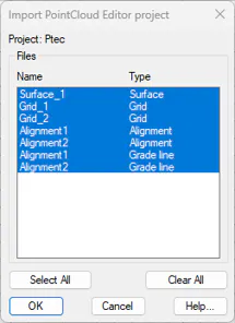
Select all elements and press OK. You can see in the panel that all elements have been imported into the project.
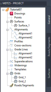
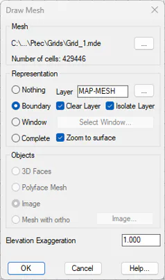
Grid_1 corresponds to the original terrain and Grid_2 to the proposed terrain. In the project content table, select Grid_1 and right-click to access the context menu and run the Draw option. To avoid overloading the drawing, select the Contour option and press OK.
Next we will calculate the volume by comparing the original terrain with the proposed one. Run Measurements> Volumes > Mesh Difference. Press OK in the following dialog, and within the folder C:/MDT26_Projects/Tutorial07/Ptec/Grids choose the files Grid_1.mde and Grid_2.mde. Activate the Draw volumes checkbox and deactivate Draw cells without volume and press OK.
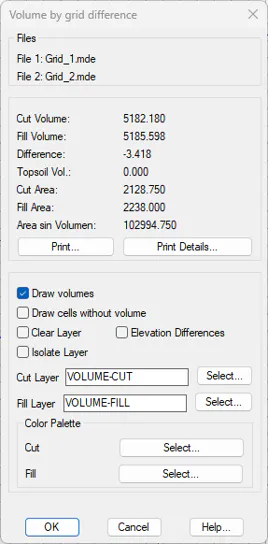
No need to draw the legend. Cut and fill areas are shown in the drawing in different colours.
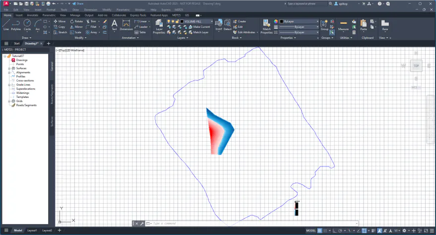
Next, in the content table, select Alignment1 and from the context menu run Draw. Repeat the operation with Alignment2.
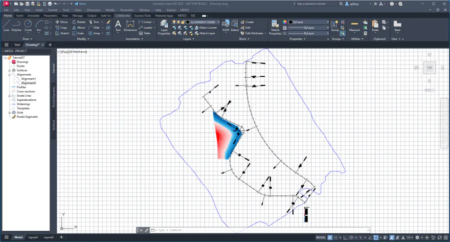
Run Cross-sections > Create from Several Surfaces. In the dialog, press Insert and add the files Grid_1.mde and Grid_2.mde.
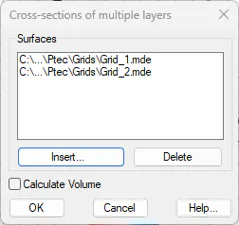
Press OK and select Alignment2, located to the west of the drawing. Set an Interval of 20 metres, a Profile Length of 80 to the Left and 20 to the Right. Press OK.
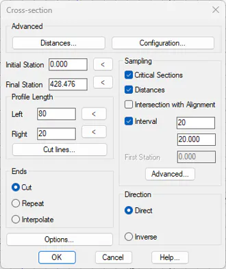
Now run Measurements> Volumes > Profile Difference and select the files Alignment2Grid_1.tra and then Alignment2Grid_2.tra.
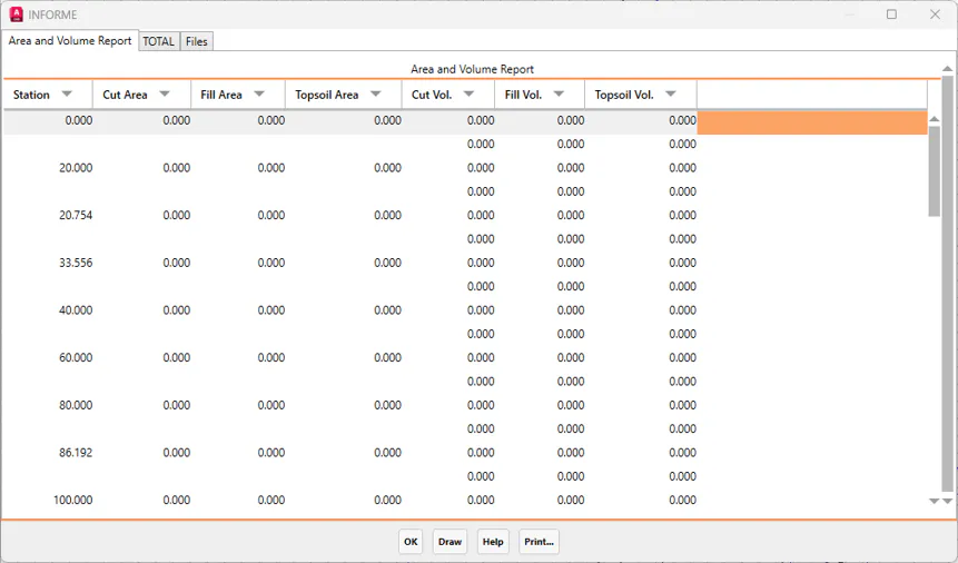
Press Draw and select the drawing options as indicated in the following figure.
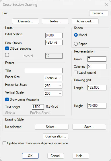
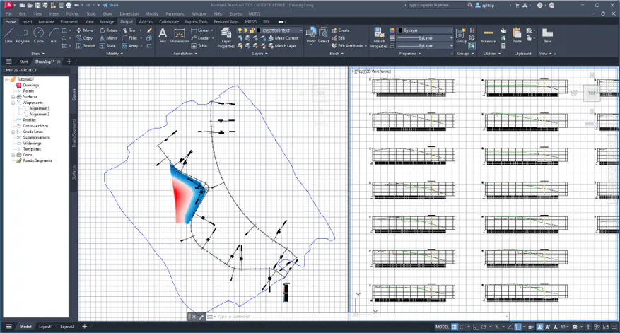
Press OK and designate a point in a clear area of the drawing.