tcpMDT
Drawing horizontal alignment - MDT25
2.6 Drawing Horizontal Alignment
Regardless of the abovementioned case for the earthwork measurement, and only for the purpose of practicing with the definition of alignments and profiles, we design a theoretical alignment with the DTM drawing and editing commands.
Then, we draw the alignment from which the profiles are obtained. Therefore, we use the command Horizontal Aligments> Draw Alignment (or Horizontal Aligments> Create> Draw).
Select origin of /Contour/Input Clothoid: 293.60,346.90
Select azimuth of /Contour/Input Clothoid: 276.77,287.22
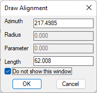
We will see the following window in which we check the Do not show this window box to continue entering the data in the CAD command line.
Select end point of /Line/Input clothoid/Verify(No)/Delete/Finish: 276.71,276.60
Select end point of /Curve/Input clothoid/Verify(No)/Delete/Finish: 286.84,238.94
Press again to end the alignment data entry.
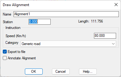
Once the alignment has been designed, the following window will appear in which we will assign the Generic Road category, check the Export to file box and disable the Annotate Alignment option, to save the alignment in file that we will name Demo2.eje.
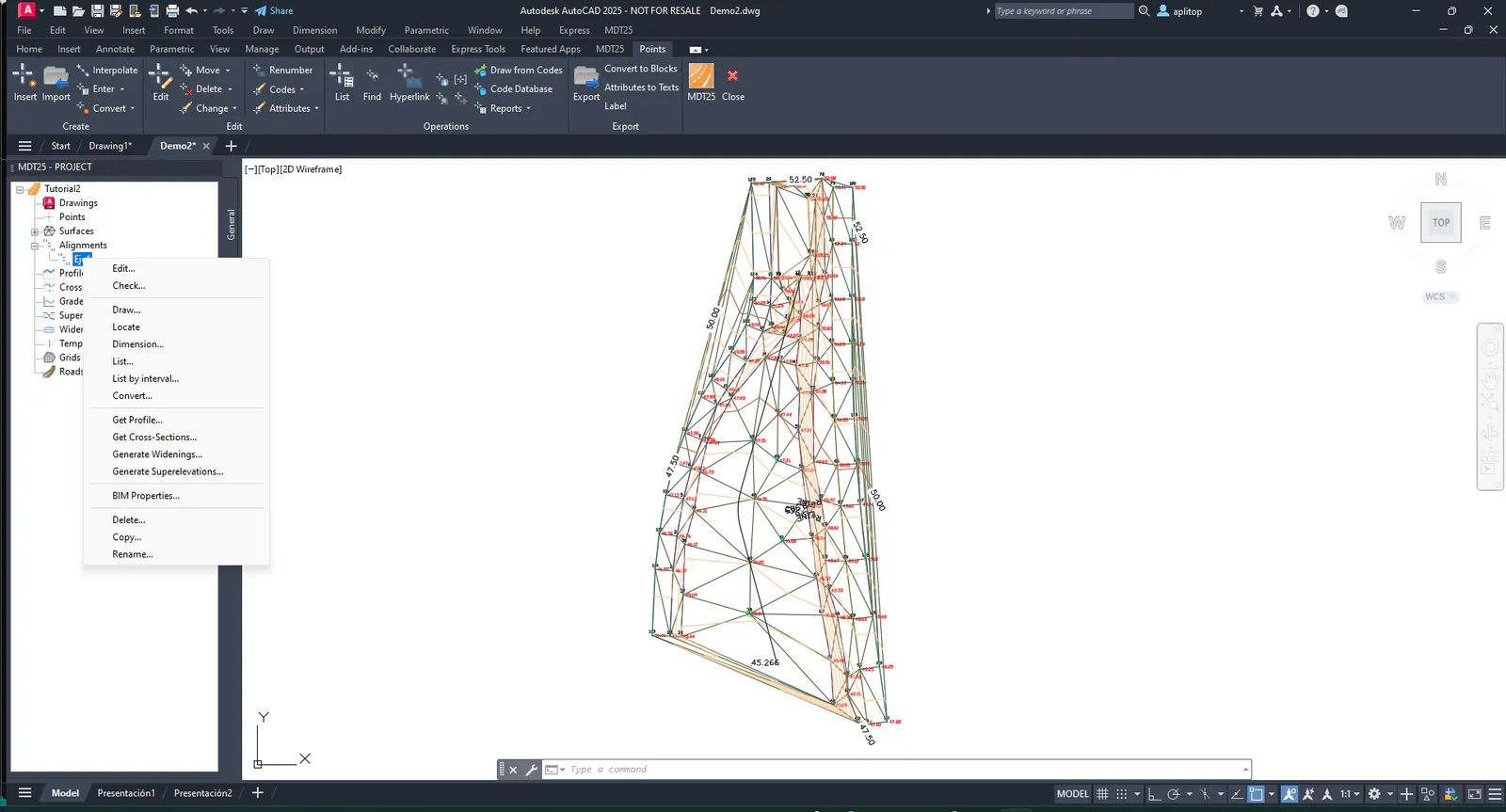
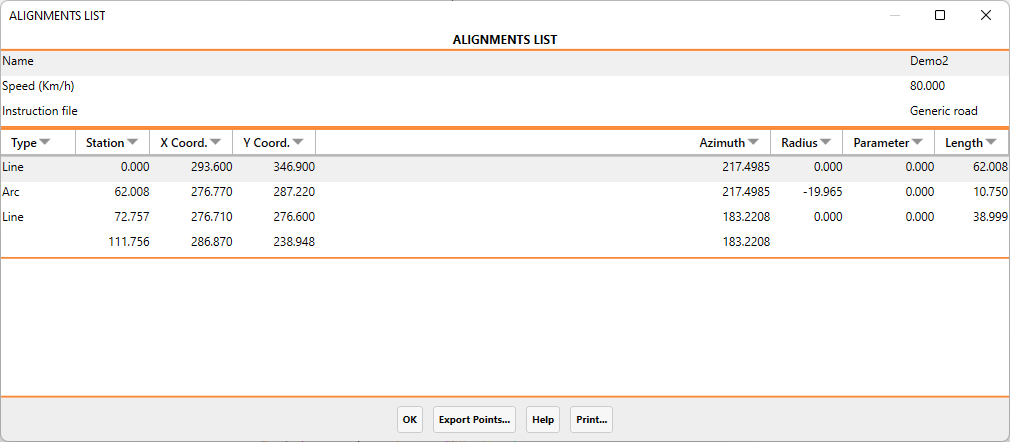
In order to know the alignments list status, we execute the command Horizontal Alignments> List Alignment (or Horizontal Alignment> Edit> List by interval), and we select the previous alignment. Press OK in the next dialog box and the program shows the alignments list, with definition of Station, X coordinate, Y coordinate, their azimuth and radius.