tcpMDT
[PRO] Analyze Points - MDT26
Analyze Points
 | Command to execute in the CAD |
|---|---|
Vertical menu | MDT26 > Setting Out > Analyze Points |
Ribbon menu | Setout > Analysis and Set-out > Analyze Points |
Command line |
Working mode
When the command is run, the command line asks for the working mode: Graphically/<Dialog>:
Dialog (default option, chosen by pressing Enter): opens the analysis dialog box described below, with the Surface, Typical Cross-Section or Vertical Alignment calculation methods.
Graphically: the analysis is done entirely from the command line. First the alignment or segment is selected, and then the points are picked on screen. For each point, the station, offset and theoretical elevation are calculated. If a segment was selected, the elevation comes from the vertical alignment or the typical cross-section; otherwise it comes from the active surface or the nearest MDT point. Picking ends when Enter is pressed, and the list of points sorted by station is then shown.
This option is primarily intended for the monitoring and control of a linear infrastructure project during construction. Its purpose is to analyze and verify a survey performed on the MDT model, generated from standard cross-sections with plan and profile alignments, which represents the theoretical terrain condition of the project. These files may have been created entirely using our applications or imported from external software.
Three calculation methods are available:
Using a Surface
Using the Typical Cross-Section
Using the Vertical Alignment
For the last two methods, the roadway segment must be specified.
In all cases, the points to be analyzed must be selected. In addition, maximum admissible positive and negative tolerance values must be defined for each method. If the difference between the actual elevation and the theoretical elevation exceeds these limits, the point is considered unacceptable and is marked with an asterisk (*).
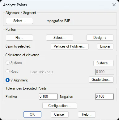
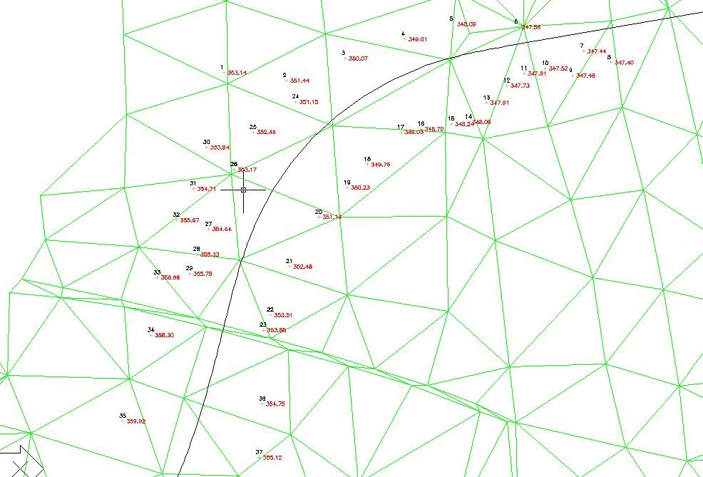
There are three methods available for selecting the points: using a point file, selecting MDT points, selecting polylines from the drawing, or specifying coordinates directly on screen.
When a point file is selected, the expected format is:
N, X, Y, Z
with the values separated by spaces or tab characters.
Surface-Based Calculation Method
In this case, the user must select the surface file against which the calculation will be performed, the corresponding alignment or segment, and the points to be analyzed.
Selecting the alignment is not mandatory if the objective is only to analyze the elevation of the points relative to the surface.
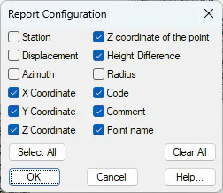
Once the dialog box has been confirmed, MDT performs the calculation process using the specified data and then displays the following window, where the report can be customized by selecting which columns should be shown.
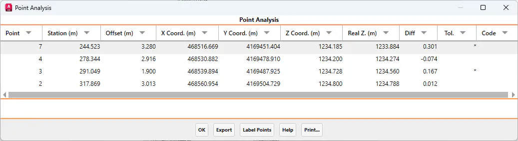
After confirming the report customization settings, the report is then displayed.
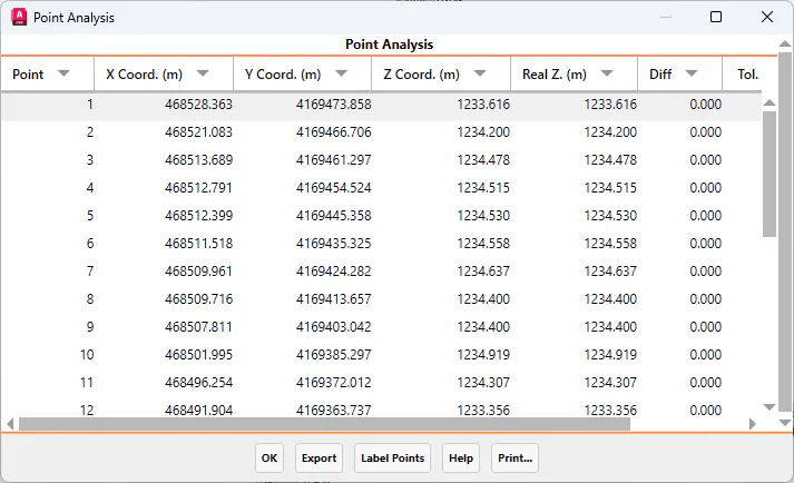
Calculation Method Using Road and Vertical Alignment
In this method, in addition to selecting the points to be analyzed, it is mandatory to select a segment instead of an alignment, since the vertical alignment or the road is required for the elevation analysis.
The points will be analyzed either against the finished cross-section or against the vertical alignment, depending on the selected option.
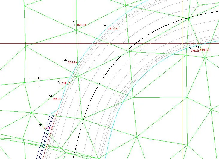
Once the MDT dialog box has been confirmed, as with the Surface option, a window will be displayed allowing the user to select the columns to be shown in the report.