
tcpMDT
[PRO] Set Out of Points - MDT26
Set Out of Points
 | Command to execute in the CAD |
|---|---|
Vertical menu | MDT26 > Setting Out > Set out Points |
Ribbon menu | Setout > Analysis and Set-out > Set-out Points |
Command line |
With this command, it is possible to calculate the coordinates of a set of points based on a previous selection made by the user.
When the command is started, the following dialog box is first displayed, where the user specifies the elements from which the points will be calculated.
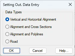
Vertical and Horizontal Alignment
The program will request an alignment and a vertical alignment, after which the following dialog box will appear, where the parameters required for the point calculation must be defined.
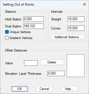
Initial Station: Starting station from which the stakeout process will be performed.
Final Station: Ending station up to which the stakeout process will be performed.
Critical Points: If this option is enabled, the critical points of the alignment will be added to the list.
Vertical Alignment Vertices: If this option is enabled, the vertices of the vertical alignment located within the segment will be added to the list.
Additional Stations: The command also allows the user to specify additional stations to be calculated.
Elevation – Layer Thickness: A pavement thickness value may be specified. The entered thickness will be subtracted from the resulting stakeout elevation. The thickness value must always be positive.
Interval: Defines the interval at which the stakeout points will be generated. A different interval may also be specified for curves.
Offsets from Alignment: The offsets, including their sign convention, to be analyzed relative to the selected alignment or segment are entered here.
Once the dialog box has been confirmed, the following window will appear, allowing the user to customize the final report.
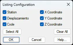
MDT performs the calculation process using the previously defined data and displays a report on screen containing the selected information.
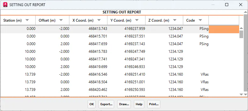
Alignment and Cross Sections
In this method, the program requests the alignment and a cross-section file. These cross-sections correspond to the roadway pavement layer from which the points are to be calculated.
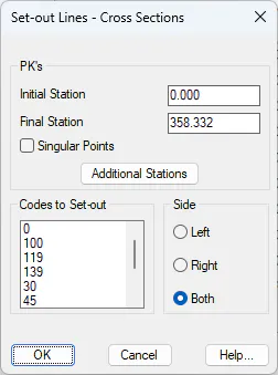
Initial Station: Station from which the stakeout process begins.
Final Station: Station up to which the stakeout process is performed.
Critical Points: Option to include alignment critical points in the analysis.
Additional Stations: It is also possible to manually include specific stations to be analyzed.
Code to Stake Out: Codes defined in the cross-sections. The selected elements will be analyzed. Multiple items can be selected from the list.
Side: Allows the user to specify whether a single side or both sides are to be analyzed simultaneously.
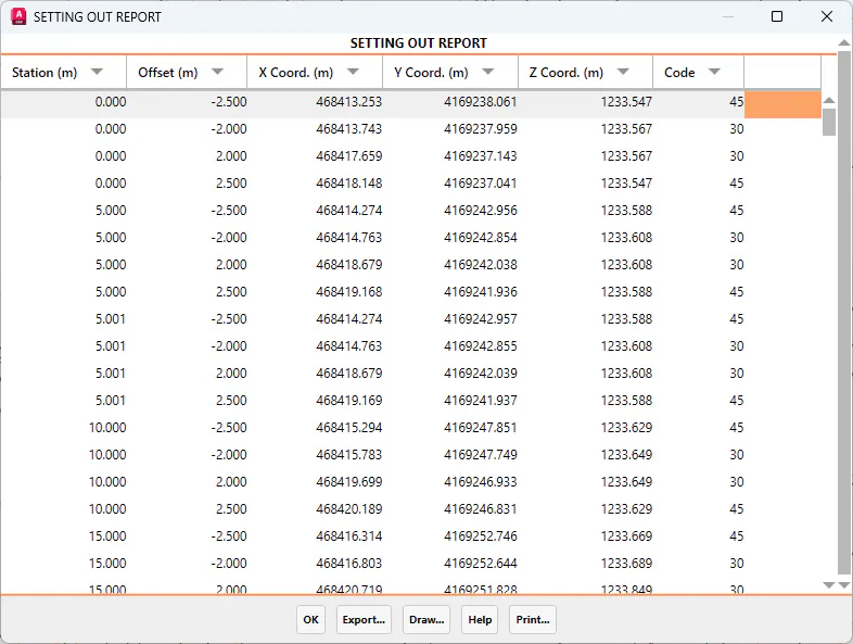
Finally, a report similar to the one shown in the following figure will be generated.
Once the dialog box has been confirmed, the program will request report customization, after which the calculated points report can be displayed.
Alignment and Polylines
In this method, the software will request the roadway segment and the set of polylines that will be used as a reference for point calculation.
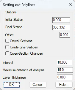
Initial Station: First station from which the stakeout calculation is performed.
Final Station: Last station up to which the stakeout report is generated.
Offset: An additional offset can be specified relative to the selected polylines. In practice, this is equivalent to analysing parallel offsets to the designated polylines, taking into account the sign convention (negative → left, positive → right).
Critical Points: The report may also include stations corresponding to the alignment's critical points.
Vertical Alignment Vertices: In this case, the vertices of vertical curve transitions are also included.
Section Change Points: All stations where a change in typical cross-section assignment occurs are included in the report. This option is only valid when working with segments.
Interval: Defines the spacing interval used for the stakeout calculation.
Layer Thickness: When staking out a segment, the program can apply a layer thickness to the calculated final elevation. This value is always positive and is subtracted from the final design elevation.
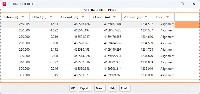
Once the dialog box is confirmed, MDT performs the calculation process using the above data and displays a report containing, for each line: the station and offset of the selected vertex relative to the alignment, the X, Y, Z coordinates, and the corresponding code of the staked-out vertex.
Road
With this option, a list of characteristic points of the cross-section is displayed.
When executing this command, a segment is first requested. This segment must include alignment, existing ground, vertical alignment, and typical cross-section information (see Segment Definition). Next, if a pavement structure is assigned, a dialog box will appear allowing the user to select the pavement layer to be staked out.
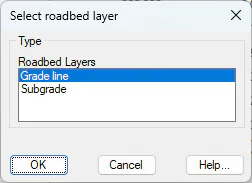
Once the pavement layer has been selected, a message will be displayed showing any possible errors detected in the segment. After confirming this message, the following dialog box will appear, where the stakeout parameters are defined.
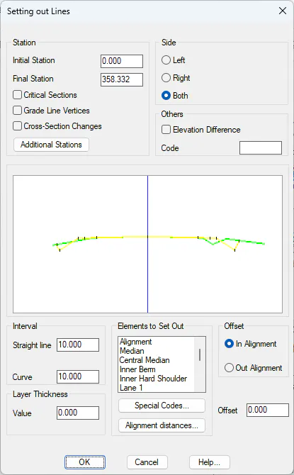
Initial Station: Station from which the stakeout is to be performed.
Final Station: Station up to which the stakeout is to be performed.
Critical Points: If this option is enabled, the alignment's critical points will be added to the list.
Vertical Alignment Vertices: If this option is enabled, the vertical alignment vertices located within the segment will be added to the list.
Section Changes: When this option is activated, all stations where a section assignment change has occurred within the alignment section assignment are included.
Additional Stations: The command can be configured to calculate specific user-defined stations.
Side: Defines the side of the cross-section to be staked out: Left, Right, or Both.
Other: When enabled, the program displays a list showing the elevation difference between the toe or crest of slope and the vertex whose code matches the value entered in the Code field.
If no code is provided, the program displays the elevation difference relative to the previous or next vertex, depending on whether it is located to the left or right of the alignment, respectively.
Interval: Defines the spacing interval used for stakeout. A different interval may also be specified for curves.
Elements to Stake Out: List of characteristic cross-section points that can be staked out. When any element is selected, it is highlighted in the preview image above, which represents the initial station of the selected cross-section. Multiple selection is allowed.
Layer Thickness: This value is subtracted from the resulting stakeout elevation. Therefore, if the value is positive, the final elevation decreases; if negative, it increases.
Offset (Setback): This parameter allows the user to apply an inward or outward offset from the alignment by a specified distance. This value applies to all selected vertices to be staked out.
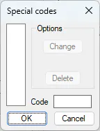
Special Codes: In addition to the elements to be staked out, one or more specific codes can be entered from which additional information is required. The following dialog is used to manage these code definitions.
Offsets from the Alignment
In addition to specifying the element to be staked out (for example, centreline, shoulder, etc.), the command also allows the user to define additional offsets from the alignment that are to be staked out, even if they do not correspond to any of the predefined elements in the list.
Once the dialog box has been confirmed, MDT performs a calculation process using the above data and displays a report on screen containing, for each line, the following information: station and offset of the selected vertex relative to the alignment, X, Y, Z coordinates, and the corresponding code of the staked-out vertex.
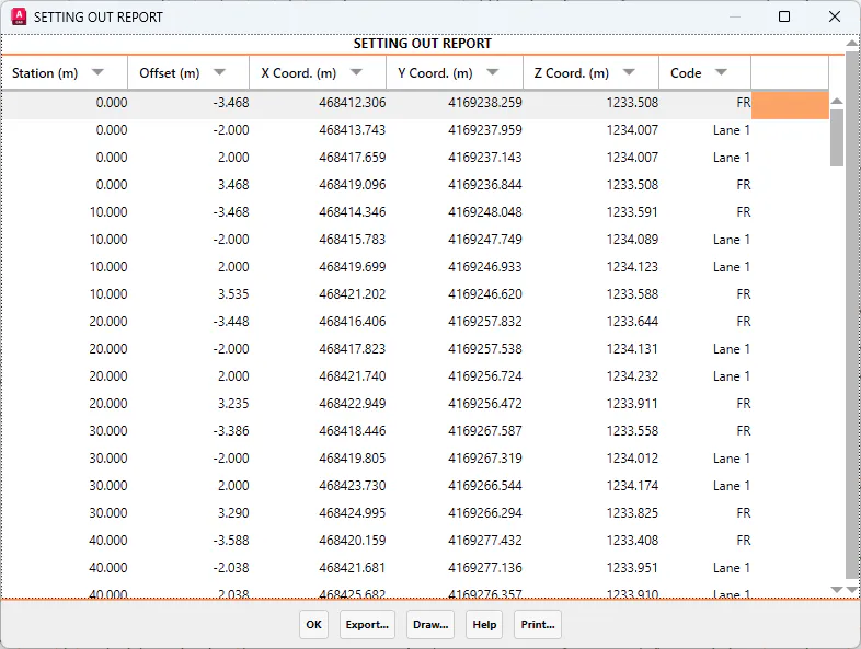
In the final report, it is possible to export, print, or draw points from the obtained data. The following options are described below:
Export
When the Export option is selected, the program displays a new dialog box offering different ways to export the data. The dialog is shown below, and its features are described in the following section:
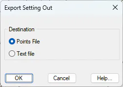
Point File: The coordinates of all points in the report are exported to a point file. When the dialog box is confirmed, the Export Points command is automatically executed. For further details, refer to the Topographic Points section.
ASCII Report: Exports the entire report content to an ASCII file, allowing it to be edited or processed using any text editor.
When this option is selected, the data from the report is sent to the selected printer for output.