tcpMDT
Earthworks with mcp - MDT26
Earthwork for a Platform
In this section the earthwork required to build a platform on the terrain modelled in the previous workflow is calculated. The assistant will automatically find the balance elevation —the one at which cut volume and fill volume are practically equal— minimising earth transport.
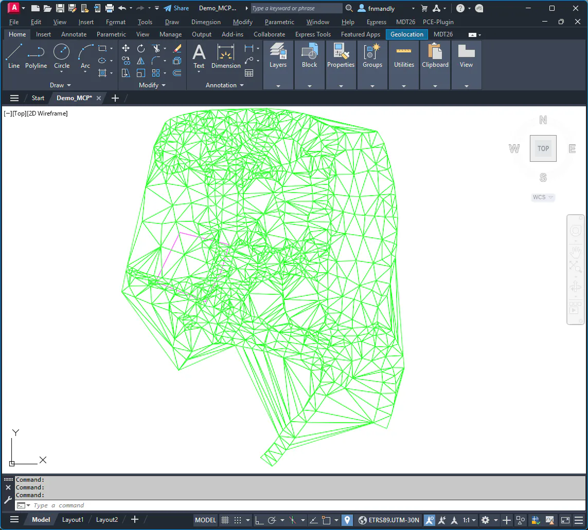
The starting point is the same Demo_MCP.dwg drawing with the active TIN surface generated in the previous workflow. The drawing also includes a closed polyline on the EXP layer that defines the perimeter of the projected platform in plan view. Using CAD tools, hide all layers except this one and the surface.
Querying the mean terrain elevation
Before setting a platform elevation, it is useful to know the mean terrain elevation inside the platform perimeter. Ask the assistant for this information:
What is the mean terrain elevation inside the platform polyline on the EXP layer?
The assistant calculates the mean elevation by interpolating the active TIN surface inside the polygon and returns the minimum, mean and maximum terrain elevations within the platform.
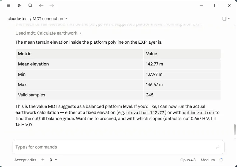
This value provides a guide for estimating a reasonable platform elevation. However, instead of manually setting an elevation, in the next step we ask the assistant to calculate it automatically.
Earthwork calculation with elevation optimisation
Ask the assistant to calculate the earthwork finding the balance elevation:
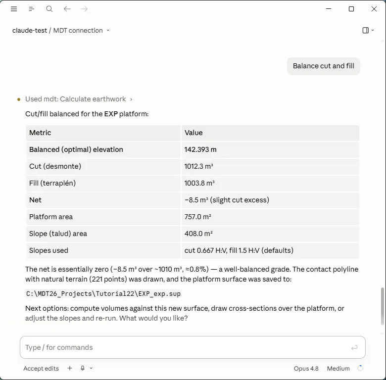
Balance cut and fill
The assistant runs the calculation with MDT's default slopes (cut 2:3 and fill 3:2) and iteratively finds the elevation at which cut and fill are approximately equal. When finished it draws the 3D contact polyline in CAD —the line where the platform slope meets the natural terrain— and creates the .sup file for the platform surface.
The assistant's response includes the optimal elevation found, the cut and fill volumes, the net volume, the platform area in plan view and the number of vertices of the contact polyline.