tcpMDT
Surface creation with mcp - MDT26
Surface and Contour Creation
With the codes identified in the previous step, we proceed to triangulate the points. First a surface without breaklines will be created to see the initial result, and then the corresponding breaklines will be added to improve the model fidelity.
Creating the initial surface
Ask the assistant to triangulate the drawing points without considering breaklines yet:
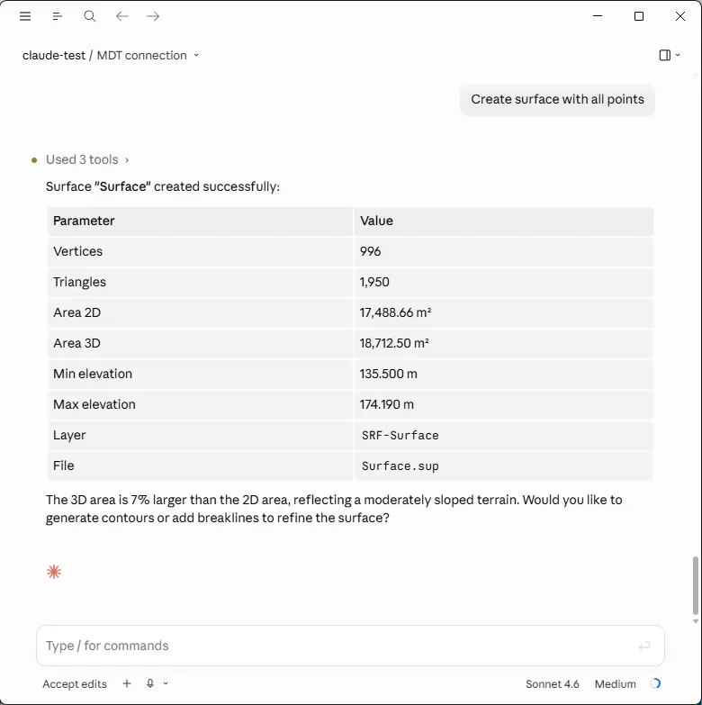
Create surface with all points
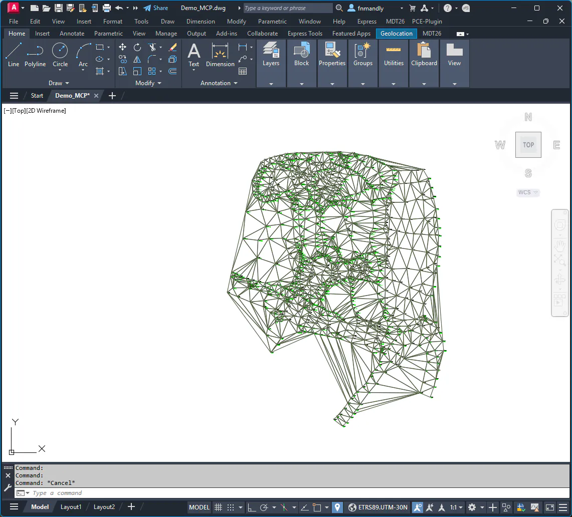
The assistant runs the triangulation and draws the TIN in CAD. When finished it returns the surface name, the number of triangles and vertices generated, the 2D and 3D area, the elevation range and the path of the .sup file created.
Drawing the breaklines
In CAD, hide the triangulation layer and type an instruction similar to the following:
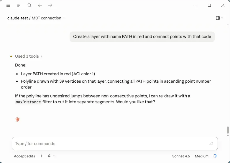
Create a layer with name PATH in red and connect points with that code
If necessary, the assistant will ask for more data.
The assistant generates 3D polylines connecting the PATH code points in order of their numbers and draws them on the PATHlayer in red.
Repeat the operation for the upper and lower slope edges.
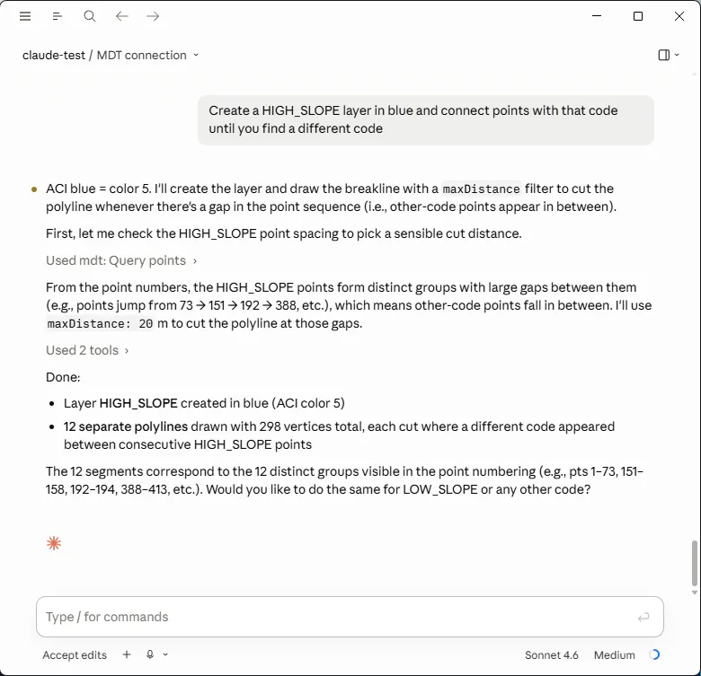
Create a HIGH_SLOPE layer in blue and connect points with that code until you find a different code
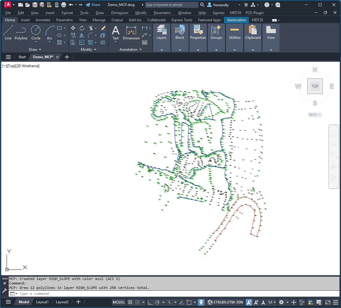
Now we create the lower slope lines.
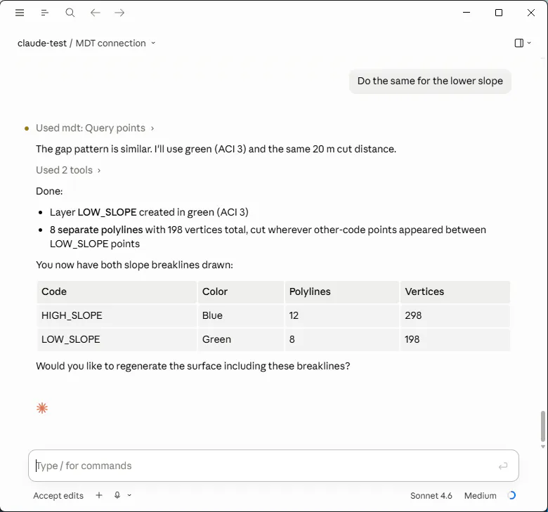
Do the same for the lower slope
The assistant draws the LOW_SLOPE code polylines on the layer of the same name.
Creating the surface with breaklines
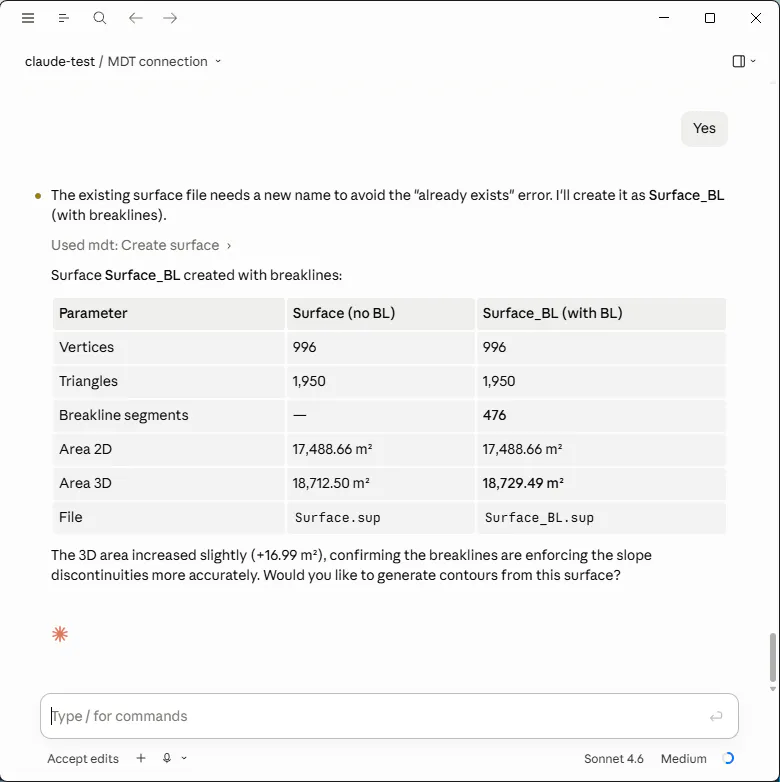
Once the breaklines have been drawn, we create the surface again using them as constraints. To do this, answer affirmatively to the previous question.
Yes
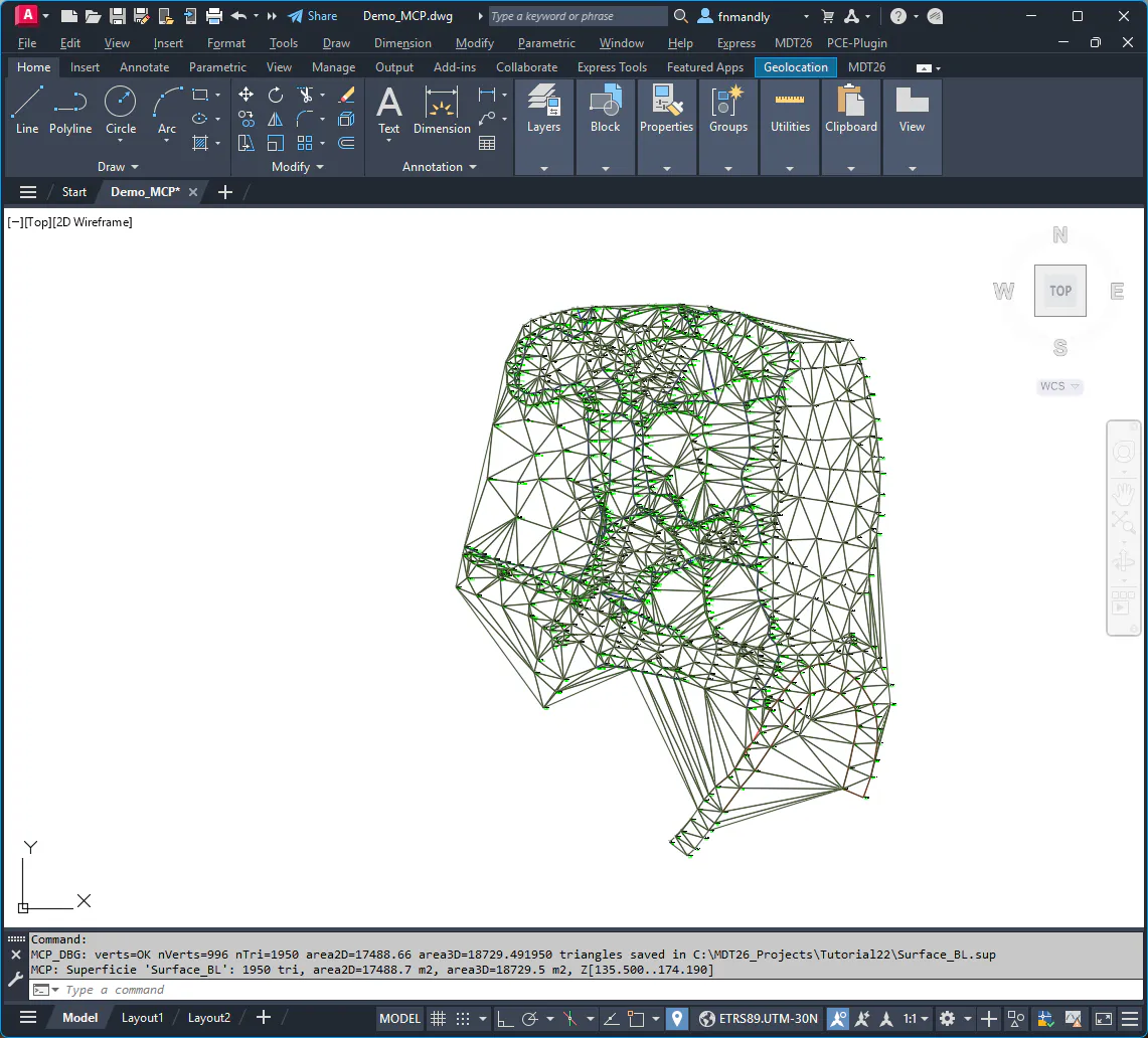
The assistant generates a new triangulation that respects the polylines on those layers as constraints.
Generating contours
Hide the points and the surface.
Now specify the interval for generating contours.
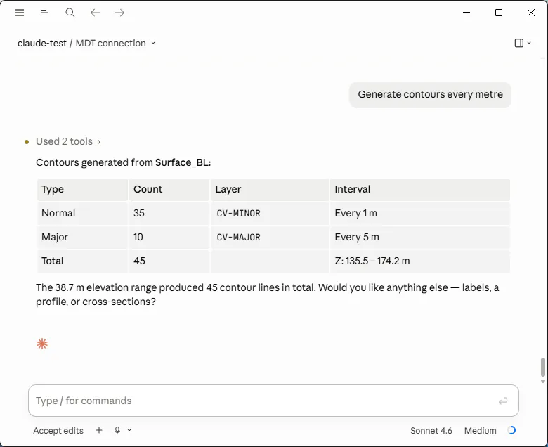
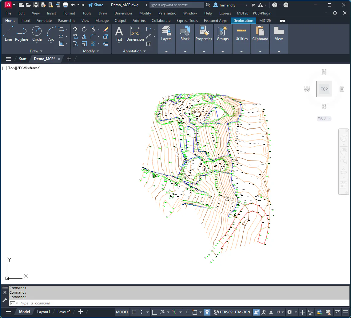
Generate contours every metre