
tcpMDT
Label Contour Lines - MDT26
Label Contour Lines
 | Command to execute in the CAD |
|---|---|
Vertical menu | MDT26 > Contour Lines/Mapping > Label Contour Lines |
Ribbon menu | Contours > Drawing > Label |
Command line |
This command allows contours to be labeled, regardless of whether they have been generated as polylines or contour objects. All the parameters that take part in the process may be edited in the window shown below:
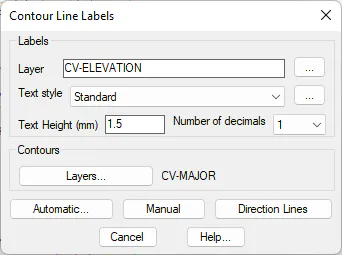
There are three options available once the Number of Decimals, Text Height, Layer and Text Style parameters have been configured.
Automatic: Positions the labels at the end and at the start of the contours drawn on any of the layers included in the list using the Layers button.
Manual: Allows the contour line to be labeled to be entered and positioned manually.
Direction Lines: By selecting two points on screen, all contours which cut across the line thus defined are labeled. This option is normally used in relatively empty areas, with gentle divides. As with the Automatic mode, the contours contained in the layers list available are analyzed with the Layers button.
All the labeling options draw the texts with an orientation which enables them to be read easily, in compliance with the labeling standards of conventional plans.
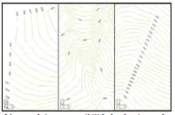
If a polyline is labeled, it is split in order to enhance the legibility of the height. But if the contour has been drawn using Contour Line objects, the same effect is achieved without altering the object. This difference means that if the labels are deleted with the Delete Labels command, the contours drawn with polylines will have gaps where the labels were to be found.