
tcpScancyr
Export cross sections to DXF - TNSB3
10.14 Export Cross Sections to DXF
This command exports a cross sections file to a DXF. In order to set up the export, you will see the following dialog box:
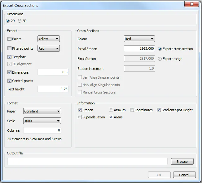
Figure 43 - Dialog box used for exporting Cross Sections
- Dimensions
The cross sections can be exported in 2D or 3D. In 3D many of the options will not be available.
- Export
Here you can indicate the various elements that make up the cross section you wish to export. All the layers you have defined are always exported. Each element to be exported (heights, surfaces, control points) has the name of the layer of which it is part as its prefix.
Points: Export the points that are close to the cross section, bandwidth is the same as in "Cross Section -> View -> Points cloud"
Template: Exports the templates that are applied to the cross section.
[TcpScancyr Advanced] 3D alignment : Exports the 3D alignment.
Surfaces: Included the various polylines that make up the under-excavation and over-excavation surfaces.
Dimensions: Includes a layer with the dimensions from the template to the cross section.
Control Points: Includes a layer with defined control points.
Text Height: Changes the size of the text showing cross sections information.
- Cross Sections
You can export a single cross section, indicating its station, or a range indicating the initial and final station. You may also stipulate their color.
If you have calculated single-point or manual cross sections, these will be marked separately on export.
- Format
Here you can specify the output format of the cross sections, in either continuous or sheet mode. You can also change the scale to adjust the drawing to the paper by using the corresponding control.
When you change values, a line will appear showing information as to how many cross sections fit on a sheet.
- Information
For each cross section you can indicate the data you wish to appear, as well as controlling its position with respect to the drawing using the left, right, up and down icons.
Station: Cross Section station
Azimuth: Orientation of the alignment in the station where the cross section was calculated.
Slope: Inclination of the vertical alignment in the cross section position.
Coordinates: X and Y coordinate of the alignment.
Gradient Spot Height: Vertical alignment height of the station.
Superelevations: Left and right superelevations value of the station.
Surfaces: Under-excavation and over-excavation surface values for each layer of the template.
- Output file
Write or select a DXF file where cross sections may be drawn. If you do not specify an output file the Accept icon will be disabled.
It is important that the selected file is not being used by any other application, nor it's write protected.