
tcpMDT
Create long section - MDT25
9.3 Create Long Section
When this option is selected, the program requests a horizontal alignment file or that a polyline be selected that constitutes the trace the profile desired. Lines and polylines are admitted as horizontal alignments. In turn, the polylines can have straight and curved sections. To process clothoid sections, it necessarily has to be a horizontal alignment. If the profile is obtained from an object other than a horizontal alignment, it does not matter in which direction it was drawn, because the program chooses the closest end to the point selected as the origin.
Executing this command displays a dialog box to define the profile requested. An overview of the process and the elements in the window are described below.
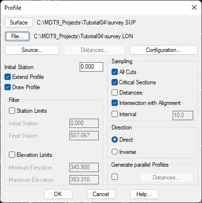
Firstly, the digital model is specified based on which it is wished to obtain the longitudinal profile. With this in mind, the Surfaces button is pressed, and surfaces or mesh file is selected based on which we wish to generate the profile if it is different from the one proposed. This option is only required in the event that we use as the data source a digital model or mesh file; otherwise, in the Source section we will select the mode or entities from which it is wished to generate the profile.
The File button shows a default directory (the current directory) in an overlaid window, together with a proposed longitudinal profile file name with a .LON extension. It is the drawing's default name. When the file name is validated or modified, the program goes back to the previous window.
The configuration of parameters involved in obtaining the profile can be accessed by clicking on Configuration.
Definition of Source
One can specify where the elevation information can be taken from to generate the longitudinal profile by clicking on Source button. This source can be:
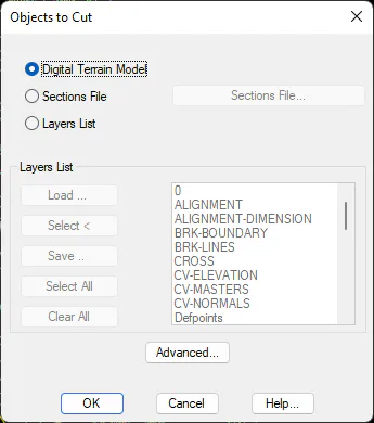
Digital Model: Indicates the current surface of the drawing. This is where the object selected to obtain the profile will be projected. This option is advisable when the model has been correctly generated, since it includes all the height and break line orientation information, enabling a precise intersection with all the elements. The file model must be selected in the Surface option of the main dialog box.
Sections file: As in the digital height model, one can indicate a previously recorded Section file (.TRM extension) using the Section File button.
Layers List: This option can be used to cut any drawing element having a height. It is very useful when working with digital mapping without the need to create large surface files. In order to do so, the cursor is pointed at the layers containing 3D elements. The digital model can also be included in the selection by marking the MDT layer. This option enables the Layers List box, from which the layers containing the 3D information can be selected.
In this latter option, if the name of the layer of an element to be considered is unknown and its position in the drawing area is known, the Select button is simply clicked. Then it goes back to the drawing mode and the program requests the corresponding objects to be selected. This operation is executed for all the objects selected.
The Save option is used when one wishes the set of layers to be saved in an ASCII file with the .CAP extension. The program displays a window entitled Save Layers List with the project directory and a proposed name for the current drawing, which can be either validated or modified. When validated, one goes back to the previous window. Once this operation has been completed, the Load button is used, as layers can be selected by simply clicking this button by choosing the layers file for jobs in any subsequent longitudinal profile or cross-section operation.
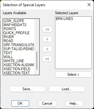
When this option is selected, the Advanced button is enabled, so that information on the objects associated to the layers is included when profiles are obtained from the layers selected in the dialog box shown below. Object heights are interpolated.
By activating the corresponding option in configuration, one can decide whether or not polylines with a zero elevation are to be cut.
Long Section Parameters
Initial Station: The initial station assigned to the horizontal alignment's initial position is entered in this box. The default value is either zero or the origin of the horizontal alignment.
Extend Profile: If the horizontal alignment or polyline from which one wishes to obtain the profile exceeds the area covered by the digital model, height is interpolated using the last two vertices found before the first or last intersection with the model at the ends of the digital model.
Draw Profile: If we enable this box, once the profile has been generated correctly, the command corresponding to the profile drawing will be executed automatically.
Sampling
This text box offers a series of options to be taken into consideration, depending on the longitudinal profile to be obtained.
All Cuts. This option informs the program to obtain cuts of all the vertices contained in the layers selected, digital model triangles or grid faces along the whole horizontal alignment.
Critical Sections. When this option is selected, the program takes into consideration the initial and final stations and all the vertices found on the horizontal alignment, in addition to all the interval distances determined prior to the constant interval: changes of orientation, vertices forming straight lines, tangents, etc.
Distance. This option allows one to include specific stations on the longitudinal profile. Activating this option enables the Distances button. A new window called Distances in Profiles is then activated.
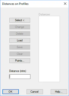
As can be observed in the window, it includes a series of buttons used for editing the stations to be included.
Select: Allows one to select the station graphically. In order to do so, either a point on the horizontal alignment is selected or a point close to the horizontal alignment indicated. The point is then projected on to itself, returning the station of the point indicated.
Change: This command changes the station selected from the list for the one indicated in the Distances text box.
Delete: Deletes the station selected from the list.
Load and Save: These commands allow one to load or generate a .DST file or a profile distance file, respectively. Each line indicates a station.
Clear: Deletes the entire list from the window.
Points: Provides access to the Point Selection window to determine the set of points whose stations one intends to project onto the horizontal alignment. See Point Selection in the Surveying Points section.
Interval: This option allows one to include a series of stations spaced out with the value indicated.
Intersections with Alignment: To use this option it is necessary to be working with a project. Once it is activated, the program will calculate the current horizontal alignment station intersections with the rest of the project's horizontal alignments.
It will include these stations in profile generation.
Filter
In this option box, one can select the part of the information about the long section that is most relevant for the job. It offers two possibilities: Setting limits between stations or elevations.
The first option allows one to indicate the initial and final station from which one intends to obtain the longitudinal profile.
Elevation limits indicate the maximum and minimum elevations permitted on the profile. If these limits are exceeded, the profile represents a flat surface at the maximum or minimum elevations shown.
Direction
In this text box, the direction in which the profile is to be obtained is specified. Direct is the direction of the horizontal alignment from the initial station to the end. Inverse, on the other hand, means that the long section starts with the final station and goes toward to the initial station.
Generate Parallel Profile
This option will allow us, in addition to generating the longitudinal of the alignment, to create additional profiles parallel to the selected alignment. With the Distances button you can add both positive and negative distances in the case that it is to the right or left of the alignment, respectively.
The name of the file will be the same as the one selected, with the suffix of the distance to the alignment.
Results
During the calculation process, elevations are obtained from drawing objects and interpolating when necessary. There is also the possibility of cutting break lines even though they have been drawn on the plan. If the Draw in 3D option is activated, the program assigns the height value to each vertex of the point that coincides with it.
The only compulsory operation when entering longitudinal profile data is horizontal alignment selection. If this is not done, the program issues the following message: "ERROR: Horizontal alignment not selected". Additionally, if the digital model is not defined and a layer to cut has not been selected, the "Layers not selected" error occurs. Another possible error consists of not having found objects cutting the horizontal alignment. In this case, the "No intersections found" error message will be displayed.
Once the generation has finalized, the following window will be displayed should it have been impossible to obtain some of the cuts specified. It provides information on any stations whose height information has not been obtained.
Additionally, in the case of generating profiles from a surface, the program will automatically detect the existence of islands or zones with an undefined surface inside the model and that affect the horizontal alignment outline. In such a case, the program will suitably list or draw the profile so as to clearly identify the location of areas with these undefined surfaces.
The file format consists of a line for each longitudinal cut found. The distance to origin (considering the initial station), the height of the terrain at this point, and a remark --which can be "Critical Section", "Constant Distance", "Specified Distance"-- or the name of the cut's layer will appear on each line.
Example: DEMO.LON
0.000 152.888 Critical Section
12.049 152.446 10050000
25.232 151.963 10050000
34.837 150.000 20010000
108.468 140.000 20010000
124.500 137.735 Distance Specified
144.079 135.000 20010000
151.677 134.451 11120000
153.921 135.000 20010000
156.594 136.093 Critical Section
166.144 140.000 20010000!
199.857 154.437 10050000!
204.713 154.729 10050000
211.550 160.000 20010000
221.007 164.758 Critical Section
221.487 165.000 20010000
293.591 175.000 20010000
301.020 172.628 10050000
314.621 175.000 20010000
327.384 175.606 Critical Section
On this fragment of a long section generated from a digital cartography drawing, cuts with contour lines (elevations with integer values) and with 3D lines (elevations with decimals) can be seen, in addition to their layer coding. Unique horizontal alignment points and a distance specified by the user have also been included.
It is also possible to see in this long section that the station codes 166.144 and 199.857 have the character "!" added to them, which marks the zones for which no surface information exists for the program.