
tcpMDT
Definition of numerical data - MDT25
9.23 Definition of Numerical Data
Users may interactively define the composition of any numerical data file by executing this command the numerical data for both long sections and cross-sections are defined by this command. Once Profiles > Definition of Numerical Data is accessed, the following dialog box is displayed:
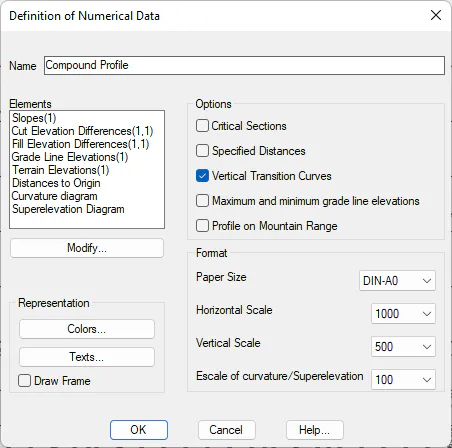
This window's characteristics are described below:
Representation
The different sizes for letters, spaces and colors of each of the elements of the numerical data that will be drawn next to the longitudinal are personalized.
Colors
When we clicked this button, a dialog box is displayed to configure the colors of the different objects drawn on the numerical data. An example of the window is shown below, and its characteristics are described.
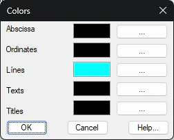
Abscissa: Establishes the color of the different horizontal lines that define the profile Drawing.
Coordinates: Establishes the color of the system of coordinates on which the profile is drawn.
Numerical data lines: Establishes the color of the different lines that comprise the numerical data.
Texts: Establishes the color of the texts marked in each of the numerical data elements.
Titles: Establishes the color of the titles of each of the elements of the numerical data.
Texts
When this button is activated, the characteristics with which the numerical data texts are to be drawn can be configured. The dialog box and a description of its characteristics appear below.
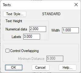
Text Style: Allows one to select the text style for the numerical data texts. MDT will display a list of the styles available in CAD.
Text Height
Numerical Data: Sets the numerical data element texts' heights.
Labels: This value represents the height of the labels associated with each of the numerical data elements.
Control Overlapping: If this box is marked, the overlap of any texts labelled will be controlled. Depending on the Minimum Distance entered, MDT will not draw any text at less than the specified distance from the previous text.
Options
Unique Points: If this control is activated, unique horizontal alignment points will be labelled when the long section or segment are represented.
Specified Distances: When this control is activated, the distances specified that are generated when the long section is obtained will be labelled on the profile drawing (see Obtain Long section command).
Vertical Transition Curves: Represents the distances corresponding to the vertical transition curves --grade line entry tangents and exit tangents-- to be represented.
Maximum and Minimum Grade Line Elevations: If we activate this box, the data corresponding to the stations featuring a maximum or minimum elevation on the vertical alignment curves will be labelled in the profile.
Saw Profile: If this option is activated, the profile may be drawn on any format, irrespective of the vertical scale selected. When the profile does not fit vertically on to the sheet, the comparison plan will automatically change and start drawing again from the bottom.
Format
Paper Size: This check box is used to select the size of the paper. One can choose among the different formats contemplated for sheet distribution (defined in the ESCALAS.DAT file). If one does not wish to split the drawing, the Continuous option (default value) should be selected.
The option exists to modify the formats proposed regarding their names, size and contents. In order to do so, the blocks in the BLOQUES\FORMATOS folder of the program's root directory should be modified.
Concerning scale fields, it is necessary to consider that the drawing's scale is determined by text size in CAD, as the drawing is only generated in a scale of 1:1 and proportionally to the horizontal / vertical relation.
Horizontal Scale: This drop-down list displays all the scales defined in the ESCALAS.DAT file in the MDT configuration directory. It is possible to complete the list with other usual values.
Vertical Scale: Same as the previous paragraph. The possibility of defining a vertical scale on the cross-section drawings has been thought up to make it possible to observe height differences in very long profiles having very small height differences without having the need to continuously enlarge the drawing on screen.
Modify
When this button is clicked, the configuration of the different elements comprising the numerical data is activated. The dialog box and a description of its functions and characteristics appear below.
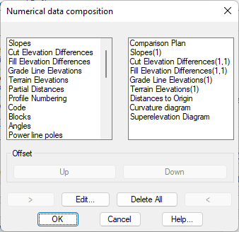
The dialog box consists of two lists. The one on the left displays the elements available and the one on the right displays the current status of the numerical data. The order latter is the order which will appear on the drawing. There are a series of controls on the bottom which help one to configure the numerical data.
Up: Any element selected on the list can be moved to a higher position than its previous position.
Down: Any element selected on the left-hand list can be moved down from its previous position.
: allows one to move an element selected on the right-hand list to the left-hand list.
<: allows one to delete an element from the left-hand or definitive list, so that it is not represented on the final drawing.
Delete All: All the elements from the left-hand list are deleted when this button is clicked, so that the numerical data will have no elements assigned to it.
Edit: Edits the characteristics of the element selected on the left-hand list.
A description of the characteristics of each of the elements available for configuring the profile numerical data appears below.
Slopes
This numerical data element will only be drawn if the segment contains a defined grade line. It represents the slope and the length of each section of the grade line.
It is possible to display various numerical data elements on the type of Slope, with reference to each of the project's vertical alignments.
The dialog box shown below is then displayed A description of its characteristics follows.
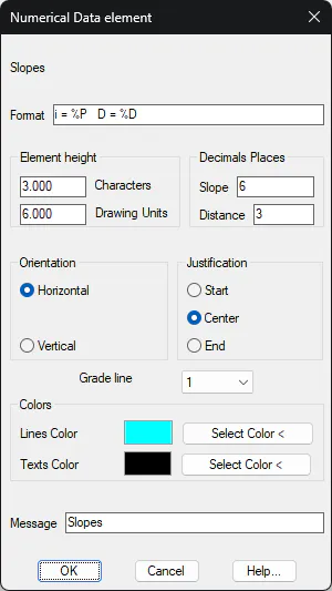
Element Height: Represents the distance to the immediately preceding numerical data element, expressed in number of characters. This value may be expressed in two different ways:
-
In number of characters
-
In drawing units
When either of them is validated, the other value is automatically recalculated.
Number of Decimal Places: Number of decimal places with which the different slopes of the longitudinal are to be represented.
Orientation: Sets the texts' orientation. If Horizontal is selected, it will automatically be represented in a vertical manner should there not be enough space due to the text's length.
Justification: Sets the position of the text in relation to the insertion point. There are three possibilities: Start, *Center and End*.
Grade line: The long section to which the element refers should be selected. By default, 1 is equivalent to the profile contained in the segment. If any another number is selected, it will be related to the profile entered in the Terrain option.
Colors: Possibility to customize the color of the horizontal line and the texts associated with the element that is represented.
Message: Text that will appear as the element's title on the numerical data drawing.
Terrain Slopes
This element shows the slope of each of the sections of the selected longitudinal profile, either by selecting the profile or from the segment.
The dialogue is then shown and its characteristics are detailed.
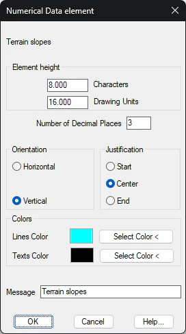
Element Height: Represents the distance to the immediately preceding element. This value can be expressed in two different ways:
-
Expressed in number of characters.
-
Expressed in drawing units.
When validating either of them, the other value is automatically recalculated.
Num. Decimals: Number of decimals with which the different slopes of the longitudinal profile will be represented.
Orientation: Establishes the orientation of the texts. If Horizontal is selected, and due to the length of the text it does not fit, it will automatically be placed vertically.
Justification: Establishes the position of the text with respect to the insertion point. There are three possibilities: Start, Center and End.
Terrain: The longitudinal profile to which the element refers must be selected. By default, 1 is equivalent to the profile that contains the segment. If we select any other number, it will be related to the profiles entered in the Terrains option.
Colors: Possibility to customize the color of the horizontal line and the texts associated with the numerical data element that is represented.
Message: Text that will appear as the title of the element in the drawing.
Cut Elevation Differences
This numerical data element will only be drawn if the segment contains a defined grade line. It represents the grade line's negative elevation difference with regard to the long section contained in the segment selected. The dialog box shown below is then displayed a description of its characteristics follows.
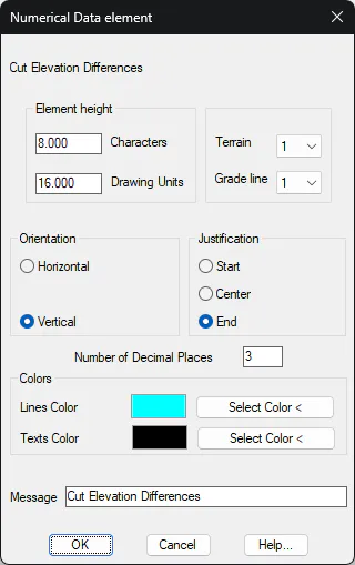
Element Height: Represents the distance to the immediately preceding numerical data element. This value can be expressed in two different ways:
-
In number of characters
-
In drawing units
When either of them is validated, the other value is automatically recalculated.
Number of Decimal Places: Number of decimal places with which the values representing cutting height differences will be represented
Orientation: Sets the texts' orientation. There are two possibilities, either Horizontal or Vertical.
Justification: Sets the position of the text in relation to the insertion point. There are three possibilities: Start, *Center and End*.
Grade Line: The grade line to which the element refers should be selected. By default, 1 is equivalent to the grade line contained in the segment. If another number is selected, it will be related to the grade line entered in the Grade Line option.
Terrain: The long section to which the element refers should be selected. By default, 1 is equivalent to the profile contained in the segment. If any another number is selected, it will be related to the profile entered in the Terrain option.
Colors: Possibility to customize the color of the horizontal line and the texts associated with the element that is represented.
Message: Text that will appear as the element's title on the numerical data drawing.
Fill Elevation Differences
This numerical data element will only be drawn if the segment contains a defined grade line. It represents the height differences of the grade line's fill with regard to the long section contained in the segment selected. The dialog box shown below is then displayed A description of its characteristics follows.
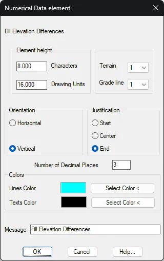
Element Height: Represents the distance to the immediately preceding numerical data element, expressed in number of characters. This value may be expressed in two different ways:
-
In number of characters
-
In drawing units
When either of them is validated, the other value is automatically recalculated.
Number of Decimal Places: Number of decimal places with which the values representing fill height differences will be represented.
Orientation: Sets the texts' orientation. There are two possibilities, either Horizontal or Vertical.
Justification: Sets the position of the text in relation to the insertion point. There are three possibilities: Start, *Center and End*.
Grade Line: The grade line to which the element refers should be selected. By default, 1 is equivalent to the grade line contained in the segment. If another number is selected, it will be related to the grade line entered in the Grade Line option.
Terrain: The long section to which the element refers should be selected. By default, 1 is equivalent to the profile contained in the segment. If another number is selected, it will be related to the profile entered in the Terrain option.
Colors: Possibility to customize the color of the horizontal line and the texts associated with the element that is represented.
Message: Text that will appear as the element's title on the numerical data drawing.
Terrain Elevation
This numerical data element represents the terrain heights of the long section contained in the selected segment. The dialog box shown below is then displayed A description of its characteristics follows.
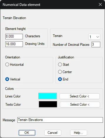
Element Height: Represents the distance to the immediately preceding numerical data element, expressed in number of characters. This value may be expressed in two different ways:
-
In number of characters
-
In drawing units
When either of them is validated, the other value is automatically recalculated.
Number of Decimal Places: Number of decimal places with which the values representing terrain heights are to be represented.
Orientation: Sets the texts' orientation. There are two possibilities, either Horizontal or Vertical.
Justification: Sets the position of the text in relation to the insertion point. There are three possibilities: Start, *Center and End*.
Terrain: The long section to which the element refers should be selected. By default, 1 is equivalent to the profile contained in the segment. If another number is selected, it will be related to the profile entered in the Terrain option.
Colors: Possibility to customize the color of the horizontal line and the texts associated with the element that is represented.
Message: Text that will appear as the element's title on the numerical data drawing.
Grade Line Elevation
This numerical data element will only be drawn if the segment contains a defined grade line. It represents the grade line heights of the grade line contained in the segment selected. The dialog box shown below is then displayed A description of its characteristics follows.
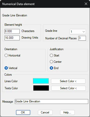
Element Height: Represents the distance to the immediately preceding numerical data element, expressed in number of characters. This value may be expressed in two different ways:
-
In number of characters
-
In drawing units
When either of them is validated, the other value is automatically recalculated.
Number of Decimal Places: Number of decimal places with which the values representing grade line heights are to be represented.
Orientation: Sets the texts' orientation. There are two possibilities, either Horizontal or Vertical.
Justification: Sets the position of the text in relation to the insertion point. There are three possibilities: Start, *Center and End*.
Grade Line: The grade line to which the element refers should be selected. By default, 1 is equivalent to the grade line contained in the segment. If another number is selected, it will be related to the grade line entered in the Grade Lines option.
Colors: Possibility to customize the color of the horizontal line and the texts associated with the element that is represented.
Message: Text that will appear as the element's title on the numerical data drawing.
Terrain Elevation Difference
This element is of enormous use for comparing the heights between two simultaneously drawn terrains. Immediately afterward the dialog box is displayed, and the characteristics are given.
Element height: Represents the immediately preceding numerical data's distance to the element. This value can be expressed in two different ways:
-
In number of characters.
-
In Drawing Units.
When validating either of these, the other value will automatically recalculate.
Number of Decimal Places Number of decimal places that will be displayed in the values representing the cut/fill.
Direction: Establishes the text direction. There are two possibilities - Horizontal and Vertical.
Justification: Establishes the text position in respect to the point of insertion. There are three possibilities: Start, Centre and End.
Terrain 1/ 2: We select the terrains between which a height comparison will be made. Previously, in the Draw Longitudinal window, in the option Terrain, the profiles we wish to compare should have been included. The order in which the profiles have been selected is the order in which they appear in the dropdown menu.
Colors: Possibility to customize the color of the horizontal line and the texts associated with the element that is represented.
Message: Text that will appear as the element's title on the numerical data drawing.
Grade Line Elevation Difference
This is the same as the previous numerical data element but in this case with the grade lines. This element will only be available in the Draw compound profile command. The dialog box is displayed below with a description of its characteristics.
Element height: Represents the immediately preceding numerical data's distance to the element. This value can be expressed in two different ways:
-
In number of characters.
-
In Drawing Units.
When validating either of these, the other value will automatically recalculate.
Number of Decimal Places: Number of decimals that will be displayed in the values representing the cut/fill.
Orientation: Sets the text direction. There are two possibilities: Horizontal and Vertical.
Justification: Sets the text position in respect to the point of insertion. There are three possibilities: Start, Centre and End.
Grade line 1/ 2: We select the terrains between which a height comparison will be made. Previously, in the Grade line option, the grade lines we wish to compare should have been included. The order in which the profiles have been selected is the order in which they appear in the dropdown menu.
Colors: Possibility to customize the color of the horizontal line and the texts associated with the element that is represented.
Message: Text that will appear as the element's title on the numerical data drawing.
Distances to Origin
This numerical data element represents the distances to the initial station of the long section to be represented. The dialog box shown below is then displayed A description of its characteristics follows.
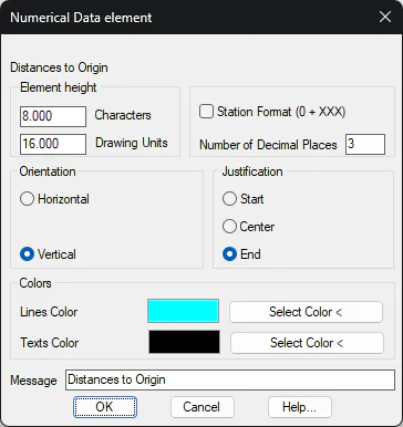
Station Format (0+XXX): If this option is enabled, one can represent the station in 0+xxx format.
Element Height: Represents the distance to the immediately preceding numerical data element, expressed in number of characters. This value may be expressed in two different ways:
-
In number of characters
-
In drawing units
When either of them is validated, the other value is automatically recalculated.
Number of Decimal Places: Number of decimal places with which distances to origin are to be represented.
Orientation: Sets the texts' orientation. There are two possibilities, either Horizontal or Vertical.
Justification: Sets the position of the text in relation to the insertion point. There are three possibilities: Start, *Center and End*.
Colors: Possibility to customize the color of the horizontal line and the texts associated with the element that is represented.
Message: Text that will appear as the element's title on the numerical data drawing.
Partial Distances
This numerical data element represents the partial distances from the long section included in the previously selected segment. The dialog box shown below is then displayed A description of its characteristics follows.
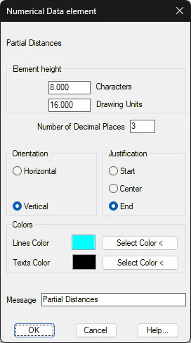
Element Height: Represents the distance to the immediately preceding numerical data element, expressed in number of characters. This value may be expressed in two different ways:
-
In number of characters
-
In drawing units
When either of them is validated, the other value is automatically recalculated.
Number of Decimal Places: Number of decimal places with which distances to origin are to be represented.
Orientation: Sets the texts' orientation. There are two possibilities, either Horizontal or Vertical.
Justification: Sets the position of the text in relation to the insertion point. There are three possibilities: Start, *Center and End*.
Colors: Possibility to customize the color of the horizontal line and the texts associated with the element that is represented.
Message: Text that will appear as the element's title on the numerical data drawing.
Profile Numbering
This numerical data element numbers each of the cuts that MDT represents on the profile drawing. The number of the initial cut in the case of long sections is set in the main dialog box. The dialog box shown below is then displayed A description of its characteristics follows.
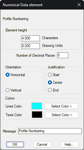
Element Height: Represents the distance to the immediately preceding numerical data element, expressed in number of characters. This value may be expressed in two different ways:
-
In number of characters
-
In drawing units
When either of them is validated, the other value is automatically recalculated.
Number of Decimal Places: Number of decimal places to be represented. It should always be zero.
Orientation: Sets the texts' orientation. There are two possibilities, either Horizontal or Vertical.
Justification: Sets the position of the text in relation to the insertion point. There are three possibilities: Start, *Center and End*.
Colors: Possibility to customize the color of the horizontal line and the texts associated with the element that is represented.
Message: Text that will appear as the element's title on the numerical data drawing.
Codes
This numerical data element labels the codes of the long section corresponding to the cut on which it is to be found. If a cut is represented that does not exist on the long section (representation by intervals, for instance), MDT will assign the immediately preceding code. The dialog box shown below is then displayed A description of its characteristics follows.
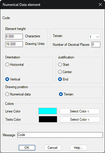
Element Height: Represents the distance to the immediately preceding numerical data element, expressed in number of characters. This value may be expressed in two different ways:
-
In number of characters
-
In drawing units
When either of them is validated, the other value is automatically recalculated.
Orientation: Sets the texts' orientation. There are two possibilities, either Horizontal or Vertical.
Justification: Sets the position of the text in relation to the insertion point. There are three possibilities: Start, *Center and End*.
Terrain: The long section to which the element refers should be selected. By default, 1 is equivalent to the profile contained in the segment. If another number is selected, it will be related to the profile entered in the Terrain option.
Number of Decimal Places: In the case that the code is a numerical value, the number of decimals displayed as applicable.
Drawing Position: This indicates whether the codes are to be labelled as another numerical data element or over the line of the profile drawn.
Colors: Possibility to customize the color of the horizontal line and the texts associated with the element that is represented.
Message: Text that will appear as the element's title on the numerical data drawing.
Curvature Diagram
This numerical data element can only be represented if a segment has been selected. It calculates the curvature diagram of the horizontal alignment associated to the segment and then draws it. The dialog box shown below is then displayed A description of its characteristics follows.
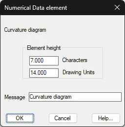
Element Height: Represents the distance to the immediately preceding numerical data element, expressed in number of characters. This value may be expressed in two different ways:
-
In number of characters
-
In drawing units
When either of them is validated, the other value is automatically recalculated.
Message: Text that will appear as the element's title on the numerical data drawing.
Superelevations Diagram
This numerical data element can only be represented if a segment has been selected. It calculates the superelevation diagram of the horizontal alignment associated to the segment and then draws it. The dialog box shown below is then displayed A description of its characteristics follows.
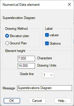
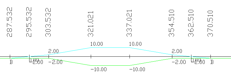
Drawing method: Represent the two ways MDT can use to draw the superelevations. An example of each of them follows.
Front View:
Top View:
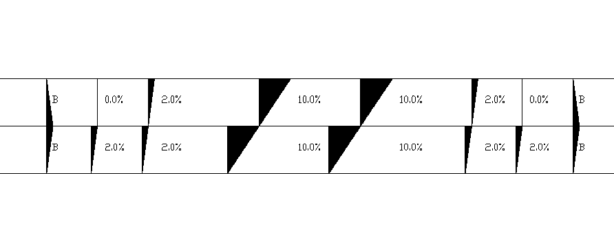
Label: Indicates whether one wishes to label both the stations and the superelevation values. These controls are only valid should the superelevation be in the elevation drawing.
Element Height: Represents the distance to the immediately preceding numerical data element. This value can be expressed in two different ways:
-
In number of characters
-
In drawing units
When either of them is validated, the other value is automatically recalculated.
Message: Text that will appear as the element's title on the numerical data drawing.
Gradient Angles
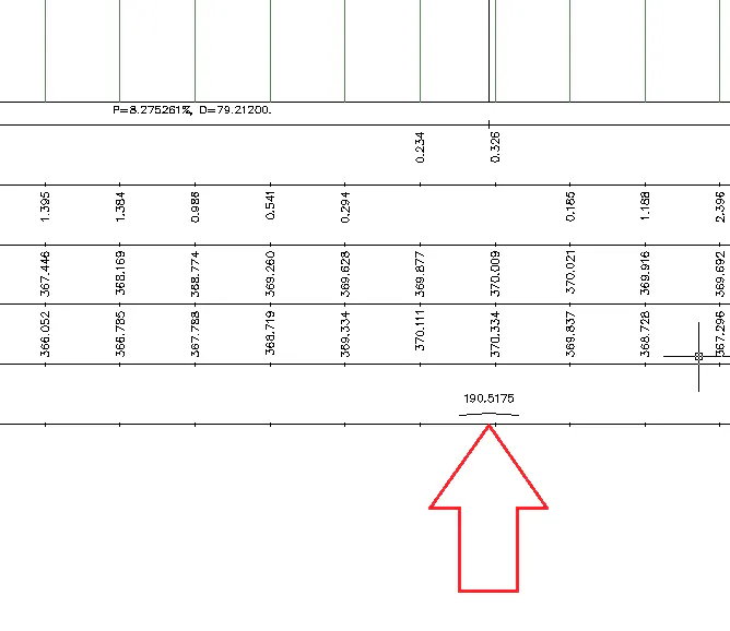
This element will allow us to label the angle at an elevation view of each of the gradient vertices. It may be particularly useful for working with pipes.
MDT will draw a new numerical data element in such a way that at each of the vertices of the gradient, the corresponding vertex will be constrained in angular terms.
This numerical data element, as with previous ones, allows the customization of the size of the text, separation, number of decimals...
A screenshot has been shown below in which the delimitation of one of the gradient vertices can be seen.
Blocks
This numerical data element is used to insert drawing blocks along the profile. In order to do so, the insertion of blocks should have been configured in the main longitudinal drawing window. For further details on configuring the representation of these, see the Alignment > Block Definition command.
Depending on how the blocks are configured, they are either inserted as another numerical data element (Numerical Data mode) or on the profile drawn (Terrain mode). The dialog box shown below is then displayed A description of its characteristics follows.
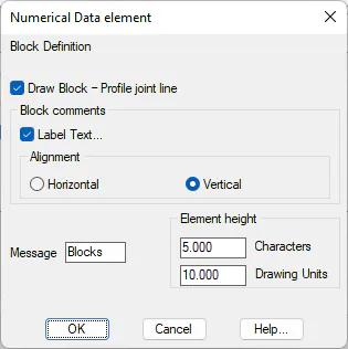
Draw Block -- Profile joint line: This option only makes sense in the case of drawing blocks over the terrain and will draw a line from the insertion point to the profile projection point.
Label Text: If we check this option, as well as drawing the block it will label the comment associated with the code corresponding to the code data base.
Alignment: Offers the choice of vertical or horizontal when labelling text.
Element Height: Represents the distance to the immediately preceding numerical data element, expressed in number of characters. This value may be expressed in two different ways:
-
In number of characters
-
In drawing units
When either of them is validated, the other value is automatically recalculated.
Message: Text that will appear as the element's title on the numerical data drawing.
Angles
This numerical data element represents the angles formed by each of the horizontal alignment's intermediate vertices. It is only valid when a segment is selected containing horizontal alignment information. The dialog box shown below is then displayed A description of its characteristics follows.
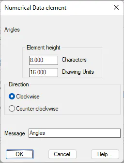
Element Height: Represents the distance to the immediately preceding numerical data element, expressed in number of characters. This value may be expressed in two different ways:
-
In number of characters
-
In drawing units
When either of them is validated, the other value is automatically recalculated.
Direction: It represents the direction in which the angle is to be taken.
Message: Text that will appear as the element's title on the numerical data drawing.
Power line poles
This numerical data element is aimed at representing power lines, although it can be used more generally. It represents the partial distance between two SUPPORT codes on the long section to be represented. The dialog box shown below is then displayed A description of its characteristics follows.
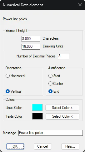
Element Height: Represents the distance to the immediately preceding numerical data element, expressed in number of characters. This value may be expressed in two different ways:
-
In number of characters
-
In drawing units
When either of them is validated, the other value is automatically recalculated.
Number of Decimals: Number of decimals with which the lengths of the partial distances between the supports are to be represented.
Orientation: Sets the texts' orientation. There are two possibilities, either Horizontal or Vertical.
Justification: Sets the position of the text in relation to the insertion point. There are three possibilities: Start, *Center and End*.
Terrain: The long section to which the element refers should be selected. By default, 1 is equivalent to the profile contained in the segment. If another number is selected, it will be related to the profile entered in the Terrain option.
Colors: Possibility to customize the color of the horizontal line and the texts associated with the element that is represented.
Message: Text that will appear as the element's title on the numerical data drawing.
Empty Element (User)
This numerical data element represents a single horizontal line without text of any kind. It is useful to manually complete the line after generating the drawing. The dialog box shown below is then displayed A description of its characteristics follows.
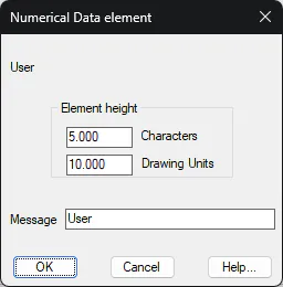
Element Height: Represents the distance to the immediately preceding numerical data element, expressed in number of characters. This value may be expressed in two different ways:
-
In number of characters
-
In drawing units
When either of them is validated, the other value is automatically recalculated.
Message: Text that will appear as the element's title on the numerical data drawing.
Defined by Parameters
The aim of this element is to allow users to label a data series concerning a numerical data element whose data is not stored in the segment but in an external file. MDT loads a file containing columns. Stations to be used as a reference should be in the first column. This column is then followed by a series of columns containing the information one wishes to label. The dialog box shown below is then displayed A description of its characteristics follows.
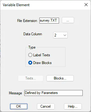
File Extension: Select the file to be used as a reference for the creation of this numerical data element.
Data Column: It is compulsory for the initial column to contain the stations used as a reference. In this command one selects the column in which the data one wishes to label is to be contained.
Type: Optionally, the possibility exists of either labelling the character chain of the column selected or drawing the block referred to by the character chain in the column selected. A different configuration for both cases. In the latter case, MDT searches for the block in the program's BLOCKS folder (see Customization Manual).
Texts
When this button is activated, the following window appears, whose characteristics are described below.
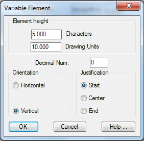
Element Height: Represents the distance to the immediately preceding numerical data element, expressed in number of characters. This value may be expressed in two different ways:
-
In number of characters
-
In drawing units
When either of them is validated, the other value is automatically recalculated.
Number of Decimal Places: If there are numbers in the texts of the selected column, they will be represented with the specified number of decimal places.
Orientation: Sets the texts' orientation. There are two possibilities, either Horizontal or Vertical.
Justification: Sets the position of the text in relation to the insertion point. There are three possibilities: Start, *Center and End*.
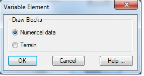
Block
If the Blocks option is selected, the position in which one wishes to draw the blocks can be set. In other words: on a numerical data element (Numerical Data) or on the profile to be drawn (Terrain).
Road Intersection
This numerical data element allows one to view the intersection points of the segment drawn compared to the segments in the same folder or project.
This option is only available for the Draw Composite Profile option.
The configuration options are as follows:
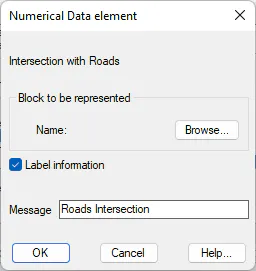
Block to be Represented Block that will be represented on the long section drawing. It will be inserted at the height of the segment with which the intersection is produced.
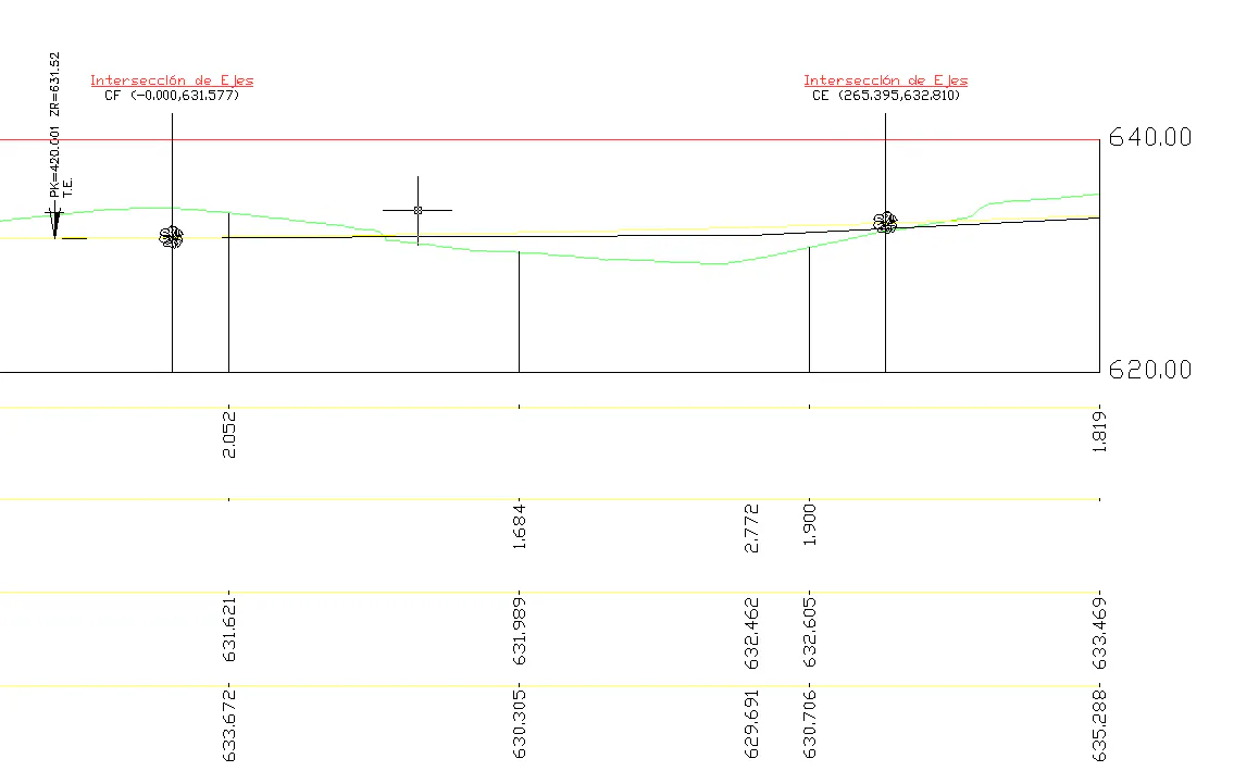
Label Information: Allows one to label information concerning the intersection with other segments. It shows the name, station and height of the intersection with another segment. A drawing where one can see how this information is labelled then displayed.
Limits
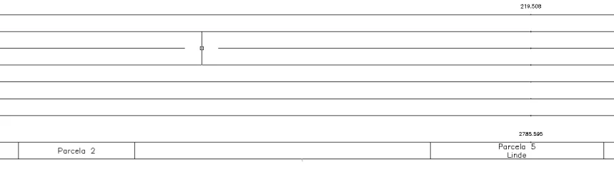
This numerical data element allows one to set limits and boundaries corresponding to the profile being drawn.
When it is edited, the following window is displayed, which is described below:
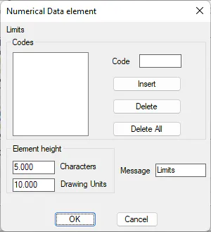
Codes: The long section's codes that will set the limits or boundaries.
Element Height: Represents the distance to the immediately preceding numerical data element, expressed in number of characters. This value may be expressed in two different ways:
-
In number of characters
-
In drawing units
When either of them is validated, the other value is automatically recalculated.
Message: Attached text that appears in this numerical data element's definition.
An example of the use of this element can be seen below:
Coordinates
This numerical data element is used to label the coordinates of each vertex represented in the profile.
Evidently this element can only be labelled in the case of selecting the segment as it has the horizontal alignment information for calculating the coordinates.
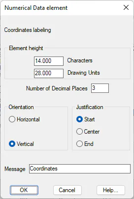
Element height: Represents the immediately preceding numerical data's distance to the element. This value can be expressed in two different ways:
-
In number of characters.
-
In Drawing Units.
When validating either of these, the other value will automatically recalculate.
Number of Decimal Places: Number of decimal places of the values representing the partial distances between supports.
Orientation: Sets the text direction. There are two possibilities - Horizontal and Vertical.
Justification: Sets the text position in respect to the point of insertion. There are three possibilities: Start, Centre and End.
Message: Text that will appear as the element's title on the numerical data drawing.
Terrain Slopes
This numerical data element will label the slope of each of the sections or vectors of the long section.
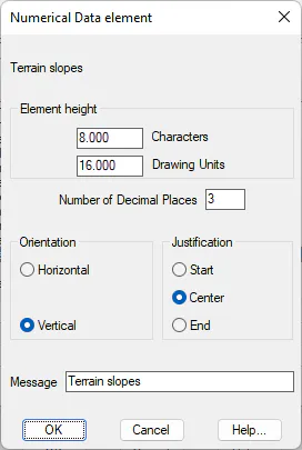
Element height: Represents the distance to the immediately previous numerical data element. This value may be expressed in two different formats:
-
Expressed in number of characters.
-
Expressed in drawing units.
On validating either of these formats, the other value will be recalculated automatically.
Number of Decimal Places: Any numbers in the text in the column selected will be represented with the decimal places indicated.
Orientation: Establishes the orientation of the texts. There are two possibilities, Horizontal or Vertical.
Colors: Possibility to customize the color of the horizontal line and the texts associated with the element that is represented.
Justification: Establishes the position of the text in relation to the point of insertion. There are three possibilities: Start, Center and End.
Message: Text that will appear as the element's title on the numerical data drawing.
Grade Line Elevation / Terrain
This numerical data element will display the height of the terrain and the height of the vertical alignment for each of the dimensioning's together.
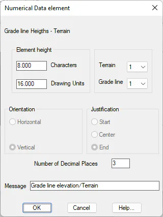
Element height: Represents the distance to the immediately previous numerical data element. This value may be expressed in two different formats:
-
Expressed in number of characters.
-
Expressed in drawing units.
On validating either of these formats, the other value will be recalculated automatically.
Number of Decimal Places: Any numbers in the text in the column selected will be represented with the decimals indicated.
Orientation: Establishes the orientation of the texts. There are two possibilities, Horizontal or Vertical.
Justification: Establishes the position of the text in relation to the point of insertion. There are three possibilities: Start, Center and End.
Terrain: We select the terrain for which the heights are to be labelled.
Vertical alignment: We select the vertical alignment for which the heights are to be labelled.
Colors: Possibility to customize the color of the horizontal line and the texts associated with the element that is represented.
Message: Text which appears as the title of the element in the numerical data drawing.
Mileage
Shows the distance to the origin in accordance with the interval configured in the element itself.