
tcpMDT
Codes database - MDT25
2.47 Codes Database
This command displays a window allowing one to view and interactively edit the Codes Database's contents.
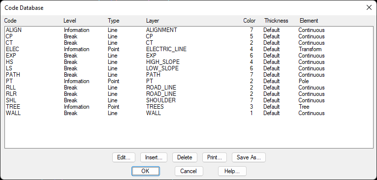
The list's parameters are as follows:
Code: Text which should coincide with a point's code. Wildcard characters such as "?" (coincides with any character) and "*" (coincides with any group of characters) can be entered. These increase the versatility of drawing from codes, avoiding the need to define more codes than is necessary.
Level: Level assigned to the points when the Classify by Levels command is executed.
Type: the type of entity drawn by the Draw command under Codes. It can be Point, Block (2P), Block (3p), Line or Area.
Layer: CAD layer used to draw polylines or insert blocks.
Color: Sets the color used to draw polylines.
Element: Depending on the Type field, can be the name of the block to be inserted if it is Point, the type of line if it is a Line, or the hatch pattern if it is an Area.
The dialog box is equipped with the following buttons:
Edit: Modifies the parameters of the code selected by displaying the dialog box called Codes Database Element.
Insert: Enters a new code into the Database. It displays the dialog box called Codes Database Element.
Delete: Deletes the code selected from the list.
Print: Generates a list of codes for the printer or stores it in a text file with a .PRN extension. It displays the List for Printer dialog box.
Codes Database Element
The parameters of the code selected can be modified by clicking the Edit button, whereupon the following dialog box is displayed:
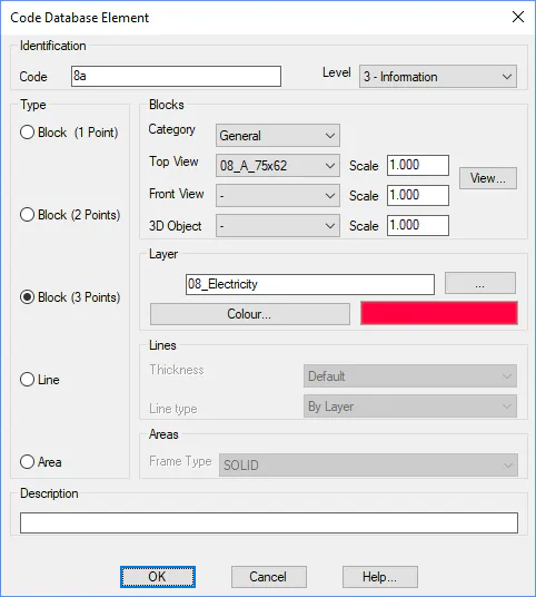
For Block (1 Point)-type elements, three different blocks can be set. Each block is classified into categories (Signs, Miscellaneous, Vegetation, etc.), we first choose a category element before choosing an element of the block types. The Top View blocks are inserted with the Draw from Codes command. When longitudinal profiles and cross-sections are drawn, Front View blocks are used at the vertices having the relevant code. 3D Object blocks are used for the Route by Terrain and Route by Road commands. Each block has an associated scale factor that is multiplied by the specific scale used by the command.
Elements of the Block (2 Points) and Block (3 Points) type are similar to Block (1 Point) elements, but only the Plane category block is used. When a code is configured as a block with two points, it is only drawn if there are two points with this code. The coordinates of the first point coincide with the insertion point of the block and the distance and direction to the second point determine the scale and rotation of the block. The program assumes that the scale of the block is 1 m, and that it is drawn horizontally, from left to right. Hence, two points (0.0.0) and (0.1.0) insert the block as defined, the scale is 1.0 and the rotation 0.0.
The program works in the same manner for blocks with 3 points, only there are two scales. One horizontal, the distance between the first and second points, and another vertical scale that calculated as the distance between the third point and the straight line between the first and second points.
Each element in the database includes a field description where once can enter a more detailed description of what the code represents. This description can be included in points lists (see List Points command).
In the Blocks section, there is an Add button for each type of block (Top View, Front View, 3D Object), if we press the Add button of the Top View type, it allows us to select a block with DWG extension, which will be copied into a new category called "User" in the user\'s block directory, therefore, these objects can be selected by choosing the "User" option from the Category drop-down. The same happens with the Add button of the Front View type. In the case of the Add button of the 3D Object type, allows us to select a file of type OBJ or FBX and then opens the Model Importer for 3D objects, where these objects can be treated for later visualization in the viewer, the object will also be added to the category "User".