tcpMDT
Import - MDT25
2.3 Import
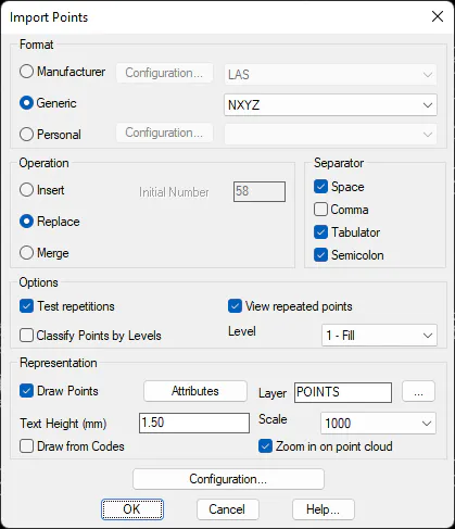
This command allows one to convert an ASCII coordinates file into points that can be read by MDT. The Import Points window dialog box requesting the parameters to be entered appears when this command is executed.
Format
The structure of the initial file is defined in the Format section, in which three alternatives are available:
Manufacturer: The format established by different programs, electronic data recorders, etc. Some of these allow various formats. Hence, the possibility exists of the configuring the structure through the Configuration button.
Generic: This option allows one to choose one of the following options from a drop-down list: XYZ, YXZ, ZXY, ZYX, XY, NXYZ, NYXZ, NZXY, NZYX, NXY and Ms Access, where N= Point number, X=X Coordinate, Y=Y Coordinate, Z=Z Coordinate. The default format is NXYZ. The former options are variations in the ASCII file's field order.
Personal: A format that can be defined by the user with the configuration file (see Customization Manual).
The character used as a field separator (Space, Comma or Tab) should be specified from Generic formats. If the Comma separator is not used, the program can import files whose decimal separator is a comma in addition to those using points as a decimal separator.
Operation
There are three ways of performing import operations:
Insert is used to add points to exiting points. The ordinal number of the points in the file to be imported is ignored and the new points are imported from the initial number entered in the dialog box.
It is the default option. Replace deletes all the drawing's points and replaces them with the points imported.
Lastly, the Merge option considers point names and only adds points to the new file whose number no longer exists in the scatter plot.
Options
One can define different processes that are executed once the points have been imported in the Options section.
Check Repetitions, the program runs different checks to identify repeated points, by name and by coordinates. Activating the option See Repeated Points displays the corresponding list.
Classify points by levels: for each point, whether its code is specified in Code Database is checked, and if so, the corresponding level is assigned. If not, the points are included in the specified Level.
Representation
For the points representation, it must be kept in mind that it is possible not to draw the imported points. This substantially increases the importation process for large files, and the size of the drawing is not increased. The points that are not drawn behave exactly the same as those that are represented, they can be listed, triangulated, exported, etc., but they are not saved in the file. Therefore, when closing the drawing in CAD the points are lost.
Drawing from Codes: represents graphic elements associated with the codes in the Code Database.
Zoom in on Points Cloud: changes the CAD view so that all the points are visible on the screen.
Finally, the Configuration button gives access to the points configuration, for which it is recommended to view the Points Configuration section.
After validating the import, the points file selection is accessed, the extension of which will accord with the format selected. The name of the file by default will be the same as the name of the drawing. The extension of the format by default NXYZ can be changed in the points configuration.
.
Points File Format
The contents of a points data file consists of a series of lines, each of which contains a series of fields separated by a separator. It is not necessary for the points to be in order. A code of up to 255 characters can optionally be included at the end of each line. A file fragment having the program's default format is shown below
Example: DEMO.PUN file
156 20329.982 10794.929 341.850 FILLING
157 20340.044 10788.699 345.510 FILLING
158 20348.481 10783.943 348.200 FILLING
159 20362.966 10773.674 357.160 EDGE
160 20374.059 10759.334 358.600 EDGE
161 20382.959 10746.893 358.260 EDGE
162 20389.362 10732.626 355.190 EDGE
163 20382.768 10719.012 355.970 EDGE
164 20374.287 10706.949 356.080 EDGE
165 20349.239 10716.461 352.050 FILLING
166 20335.434 10720.082 350.390 FILLING
167 20311.123 10726.424 347.120 FILLING
168 20291.163 10730.610 344.910 FILLING
169 20363.322 10785.258 355.040 EDGE
170 20350.357 10790.070 347.270 FILLING
171 20340.376 10794.961 343.950 FILLING
Importing Raw GPS Data
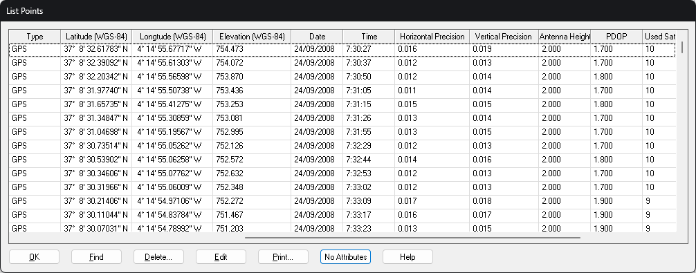
If the points have been taken using the TcpGPS application and the raw data file is in the same folder as the coordinates file, other attributes will be imported such as the date and time, type of position, latitude and longitude, antenna height, number of satellites, etc. Moreover, the horizontal and vertical positions estimated by the receiver are assigned to the coordinates as uncertainties. See the Geodesic Calculations chapter in the User Manual for further details.
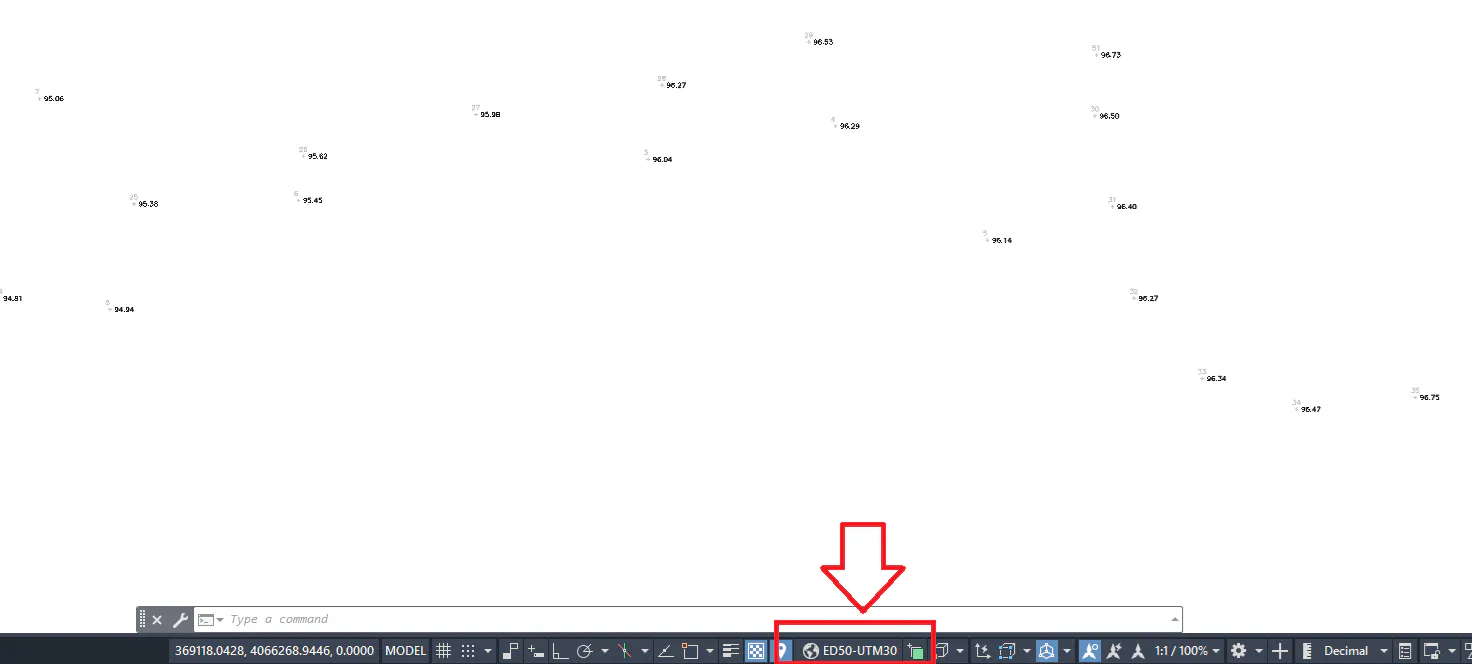
In addition, it will read the information related to the projection in the file of the TcpGPS application and assign it to the current drawing. This option is only available for CAD versions that support this feature.