
tcpMDT
Draw from codes - MDT25
2.42 Draw from Codes
This tool is used to draw a set of graphical elements (blocks, lines and areas) from the drawing's point codes and the shared Codes Database for all the projects.
When this command is executed, one can select the range of points one wishes to work with and if all or just one of the database's codes are used by clicking on the Select button. The option Consider Suffixes is used when drawing lines to define whether the program will account for the suffixes at the beginning, end, line close, etc.
Moreover, the Use sets of alphanumeric points option enables us to use the command for sets of points shared by the same prefix in its name. Hence, the program covers the points with a numeric name from the initial to the final point, and then covers these points separately for each existing prefix.
One can also choose if the program should delete the objects drawn on the corresponding layer before drawing, in addition to specifying the scale with which blocks will be inserted.
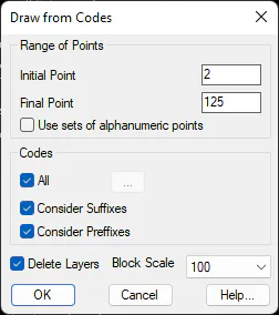
By running this command, you can select the range of points on which to work. The Use set of alphanumeric points option allows you to use the command over sets of points that share the same prefix in their name. Thus, the program goes through the points with numerical name from the starting point to the end, and then for each prefix that exists, those points are traversed separately.
By default, the program will consider all the codes in the database, but by pressing the "..." you can choose only one in particular. The Consider Suffixes option allows you to select whether when drawing lines, start, end, line closure suffixes, etc. are considered. With the Consider Prefixes option, it can be done that, if the points include a number at the beginning of the code, this is considered when drawing lines so that each of the prefixes are drawn separately.
One must consider that if a point has various codes separated by commas, each of them will be processed independently.
Drawing Blocks
Blocks are inserted at any points whose code has been defined in the Codes Database as point type and when the block has been specified on the associated ground plan.
The blocks must be saved as independent drawings (DWG format) in the Plant subdirectory, within one of these two directories:
-
User block directory, which can be specified in the parameter with the same name with the command Tools > Configuration > General.
-
The program installation block directory. By default, "C:\Program Files\Aplitop\MDT9\Bloques\en" in an English installation, if no other installation directory is specified.
These blocks are inserted in the layer specified in the database. Each block's insertion point will coincide with the associated point's coordinates.
Drawing Lines
Polylines are drawn with the coordinates of points whose codes are defined in the Codes Database and line-type points. Additionally, the layer, color and polyline line type are specified in the database.
The program runs through the points in numerical order and begins to draw a polyline when it discovers a point with a code that is included in the database. Depending on whether the suffixes are accounted for, it checks that the code has the indicative polyline starting text " I" (a space followed by the letter I). Then it continues to draw vertices as it discovers points with the same code (consecutive or not but respecting its order). If the suffixes are accounted for, there are three possibilities for finishing the polyline:
-
Code followed by the end of polyline identifier, "F" (space followed by the letter "F").
-
Code indicating the start of a polyline. The current polyline is ended in the previous point and a new polyline is commenced.
- Code followed by the close polyline identifier, "C" (space followed by the letter "C"). In this case, a closed polyline is drawn that links the last point with the first.
Polylines can additionally contain arch segments. For this, "CI" suffixes should be used for the start point, "CC" for the intermediate points and "CF" for the final point. See Surface Configuration, Break Line Coding button.
Example: TEST.PUN file
1996 5045.832 1061.510 501.879 PT I
1997 5044.845 1071.420 501.732 PT
1998 5043.683 1081.993 501.461 PT
1999 5043.091 1088.787 501.167 PT
2000 5041.971 1093.391 500.915 PT
2001 5030.666 1108.028 501.395 PT
2002 5024.684 1110.593 501.910 PT
2003 5031.066 1101.000 504.437 PT I
2004 5034.107 1099.849 504.126 PT
2005 5035.346 1098.567 503.982 OF
2006 5036.670 1097.461 503.671 PT
2007 5038.556 1092.508 503.063 PT
2008 5039.016 1088.253 503.584 PT
2009 5038.387 1082.490 504.113 PT F
2010 5037.174 1080.777 504.417 CP I
2011 5038.500 1080.918 504.286 CP
2012 5037.571 1073.691 504.841 CP
2013 5038.561 1073.683 504.699 CP
2014 5037.641 1066.026 505.287 CP
2015 5039.541 1066.738 505.105 CP
2016 5037.979 1056.046 505.906 CP
2017 5039.174 1056.121 505.826 CP
2018 5037.459 1052.331 506.239 CP
2019 5038.846 1052.464 506.155 CP C
Supposing the PT and CP codes were defined in the Codes Database line-type points and assigned to a layer with the same name, this file would have been drawn as follows:
New Polyline in PT layer, joining points 1996-1997-1998-1999-2000-2001-2002.
Polyline having the same characteristics joining points 2003-2004-2006-2007-2008-2009.
Polyline in CP layer, joining points 2010-2011-2012-2013-2014-2015-2016-2017-2018-2019 and closing with 2010.
Example: File TEST2. PUN
100 4666.105 5264.065 123.000 1PATH S\ 101 4667.592 5262.728 123.020 2PATH S\ 102 4762.394 5371.143 124.400 1PATH\ 103 4763.686 5369.590 124.433 2PATH\ 104 4898.651 5454.628 125.120 1PATH\ 105 4899.460 5452.778 125.119 2PATH\ 106 5098.495 5510.889 124.565 1PATH
Assuming that the PATH code was defined in the BDC as linear, and activating the option to Consider Prefixes when drawing from codes, this file would draw two polylines on the same layer, one with the points 100, 102, 104, 106 ... and another with points 101, 103, 105...
If the Consider Prefixes option is not activated, then to draw two polylines you would have to register in the BDC both codes: 1PATH and 2PATH.
Drawing Areas
This option is similar to the previous one, as the program draws a set of polylines with the same criteria as in the case of the lines. The difference lies in the fact that if Type code in the Codes Database is Area, the program always automatically closes all polylines and then fills them in using a hatched pattern.