tcpMDT
[PRO] Earhworks - MDT26
Earthworks
 | Command to execute in the CAD |
|---|---|
Vertical menu | MDT26 > Measurements > Volumes > Earthworks |
Ribbon menu | Volumes > Road > Earthworks |
Command line |
This command generates a complete list of the surface areas and volumes in a segment. It displays the cut, fill and topsoil areas and volumes by station, as well as their accumulated values.
MDT initially requests the segment file containing all the project's information (see Definition of Segment in the Roads section), in other words, information on the grade line, the natural terrain, cross-section template, etc. Once it is selected, the following dialog box is displayed where the parameters of the list one wishes to obtain are set.
The user has the option of selecting several segments simultaneously, whereby the cubic measurement will be calculated for each of the segments in an independent list. This avoids the execution of the command once for each of the segments we need to calculate.
If the user selects multiple segments simultaneously, located in the same folder, a report will be displayed with the total cubing of each of the road segments:
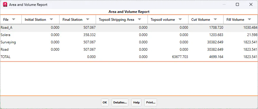
Pressing the Details button will perform the cubing of the segment selected in the list, as described below.
The dialog box's characteristics and functionalities are described below.
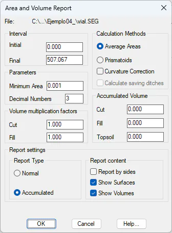
Initial Station: Station from which the volume measurement will be calculated.
Final Station. Station up to which the volume measurement will be calculated.
Report by Sides; In the final list, it allows you to break down the calculation according to the side of the axis, performing the calculation to the left and right of the alignment.
Minimum Area: Sets the minimum surface admissible area on the report. Any values that are lower are considered as zero. It is used to prevent accuracy or rounding off errors that could lead to confusing results.
Number of Decimals: Sets the number of decimal places with which one wishes the volume measurement calculations to be displayed.
Accumulated Volume
These values are assigned to the respective volumes, so the initial station on the list has this initial value.
Cut: Accumulated cut value. MDT will start off with the value entered in this field as the cut value.
Fill: As above, but for fills.
Topsoil: Same as above, but for the topsoil.
Calculation Methods
There are two different methods to calculate the volume associated to a cut, fill or topsoil.
Average Area Method
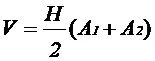
In this case, the volume is calculated using the following formula:
where:
V = Volume between the current and the previous station.
H = Interval between the previous and the current station.
A~1~ = Area of the previous station.
A~2~ = Area of the current station.
Prismatoid Method
In this case, the formula is as follows:
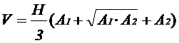
where:
V = Volume between the current and the previous station.
H = Interval between the previous and the current station.
A~1~ = Area of the previous station.
A~2~ = Area of the current station.
Curvature Correction
If this box is marked, the impact of curvature when calculating the volumes is considered. The formula employed is as follows:
where:
C~C~ = Curvature correction to be added to the total volume
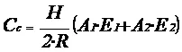
H = Interval between the previous and the current station.
R = Radius of the curve.
A~1~ = Area of the previous station.
A~2~ = Area of the current station.
E~1~ = Distance from the previous profile's center of gravity to the horizontal alignment
E~2~ = Distance from the current profile's center of gravity to the horizontal alignment
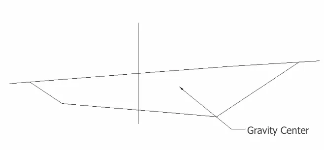
In order to calculate a profile's center of gravity, a traverse containing all the vectors of the natural terrain and the profile generated is constructed. Then the following formula is applied:
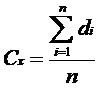

where:
C~x,~C~y~ = X and Y coordinates of the center of gravity
d~i~ = Distance from vertex i to the horizontal alignment
z~i~ = Area of the previous station.
From this calculation, E is assigned the value of C~x~~,~ with its corresponding sign.
Saving Ditch
If there are saving ditches defined in the segment, by activating this option the program will automatically calculate the total volume of this element definition.
Factors
These values are factors which multiply the values calculated for the respective surfaces. They can be used to consider the bulking or compacting of earth when making volume measurement calculations.
Cut: Multiplying factor for the cut area.
Fill: Multiplying factor for the fill area.
Report Types
Normal: In this case, a list containing each profile's area and volume calculations is displayed.
Accumulated: In this case, the accumulated areas and volumes for every two stations up to the current station are displayed on the list.
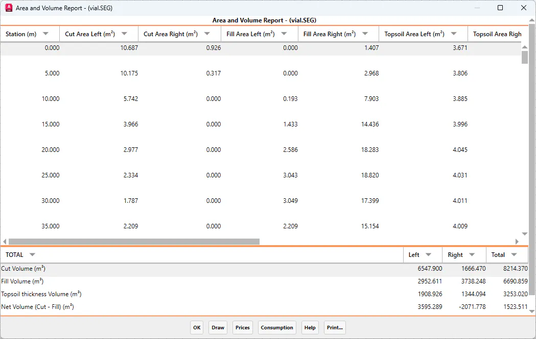
Once the dialog box is validated, the following list is displayed showing the final volume measurement (net difference).
Options
Volume Calculation by Side: In the final report, the calculation can be broken down according to the side of the centerline, performing separate calculations for the left and right sides.
Display Volumes and Surfaces: Allows the report configuration to display volumes, surface, or both.
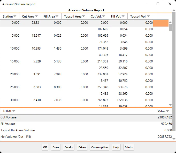
When the dialog box is finalized, totals along with the difference between cut and fill will be displayed.
The dialogue box features the following options:
Draw: Clicking on this button will draw the segment (see Draw Cross-sections in the Cross-sections chapter).
Excel: All the information in the list will be placed on an Excel sheet. This Excel sheet features totals with an equation, whereby changing any value will automatically change the end result of the corresponding column.
If the Volume Calculation by Side option is enabled, the resulting report will be similar to the following example, where each side of the cross-section is calculated independently.