tcpMDT
[PRO] createedit - MDT25
13.2 [PRO] Create/Edit

This command is used to define a segment file (extension .SEG). This file will include all files generated over the course of our project associated with each horizontal alignment, in order to integrate all the information and avoid having to request each part individually in all the commands required. It is comprised of the following elements:
Current Surface: Surface with which the segment will work in the case of generating the different components in this editing window.
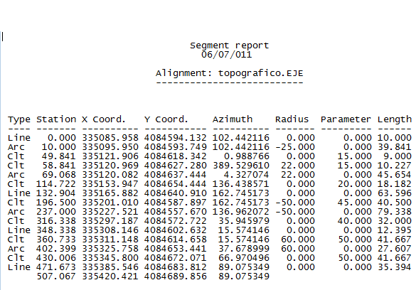
Horizontal alignment (extension .EJE): the most important file, as all the other files are associated with this one. Obligatory.
Long Section (extension .LON): contains the longitudinal profile associated with the horizontal alignment. Obligatory.
Cross-sections (extension .TRA): contains the cross-section profiles associated with the horizontal alignment. It is not essential to draw complete longitudinal profiles, although it is to draw cross-section profiles and cubic measurement lists.
Vertical Alignments (extension .RAS): contains the vertical alignment associated with the horizontal alignment and the longitudinal profile. It is necessary both for the complete longitudinal profile drawing and for the calculation and drawing of the cross-section profiles.
Widenings (extension .SOB): contains the shoulders associated with a horizontal alignment if they exist. Optional.
Templates (extension .SCC): contains the section definition and assignment across the horizontal alignment. These are necessary to calculate and draw the cross-section profiles.
Superelevations (extension .PER): contains the superelevations associated with a horizontal alignment if they exist. Optional.
Blocks (extension .BLK): contains the block assignment definitions to represent in the drawing, of the roads or the profiles. Optional.
Skewed Cross-sections (extension .TRE): contains the skewed cross-sections definitions that could be generated from the horizontal alignment. Optional.
In order to facilitate its use, the content of each of these files is copied to the segment file in binary format, meaning, they are not linked to the original files but are embedded in them. Therefore, if any changes are made to one of these files using the different options the command provides, the original file will not change, though once we validate this dialogue box, the command will notify us of said circumstances and we can update the files that were originally imported with the current information.
After activating it the MDT command requests a segment file, which can be a new file or an already-existing file. Once it is selected a dialog box like the one below will appear, which details the characteristics of the segment, meaning, the elements or files it contains. The following is a description of the characteristics of each of the controls in the dialog box.
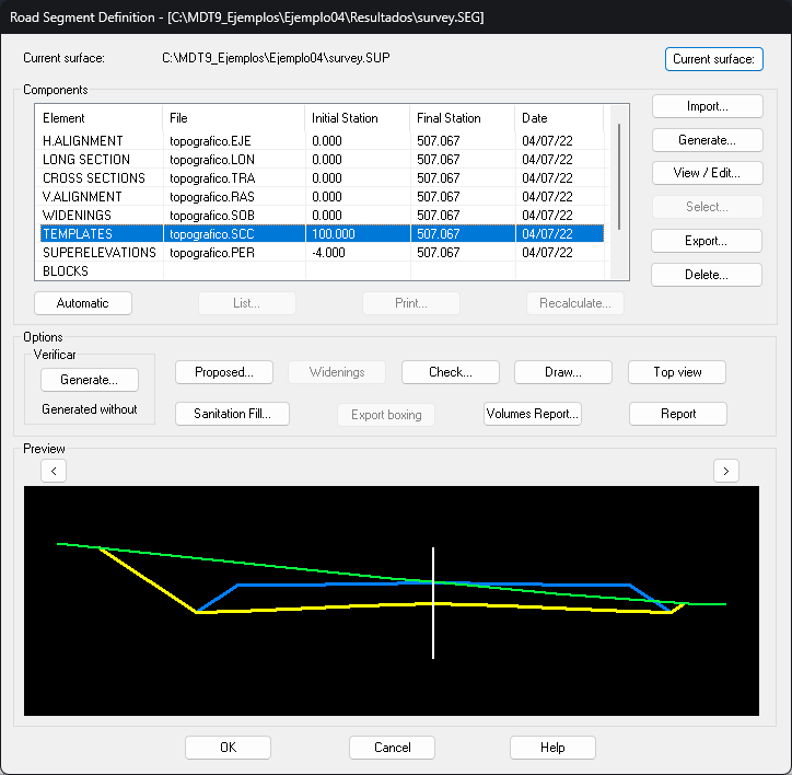
Three differentiated sections can be distinguished.
Components: Refers to each one of the linked files.
Options: Different options for the segment for once the different segment elements have been imported.
Preview: Drawing representing the element selected in the section Components.
Components
This section features the different elements the segment contains, as well as the different buttons for interacting with them. Their functions are described below.
The date field is filled in whenever the file that it refers to is found on the computer, showing its date.
Import: Depending on the element selected, by pressing this button MDT requests the respective file and once selected this becomes a part of the segment. For example, if the Long Section option is activated by pressing this button the program will request a file with the file ending *.LON.
Automatic: Pressing this button automatically imports all the files found in the same folder as the segment and with its same name.
Select: This option is only accessible for the horizontal alignment, the long section and the vertical alignment. It allows us to graphically select the element instead of importing it necessarily from a file.
Export: Similar to the previous button, by pressing this one MDT will export the selected element to a file. This option is very useful for updating information if the segment content has been modified in a command later executed.
Delete: Deletes the information the segment of the element has associated with the element selected.
View/edit: Enables visualization of the element selected. Editing is carried out on an external editor and changes can be made on the majority of the elements, but these changes will only be kept for the segments and not the files they depend on. To update the files, use the Export option mentioned previously.
List: This enables listing the elements selected. Changes can be made to the lists, but these changes will only be maintained in the segments and not in the files they depend on. To update the files, use the option Export mentioned previously.
Generate: This option is another alternative to importing. For superelevations and shoulders it is only necessary to define the horizontal alignment. To make it possible to use these with longitudinal profiles and cross-sections, it is necessary to have a surface and its respective files defined. MDT analyses them to extract the interval between profiles and then recalculates them, updating the information.
For long and cross sections, in the event that there is no active surface, the surface file will be requested to generate the profiles. Subsequently, the generation will be managed in the same way as described in the long and cross sections chapters.
In the case of the grade, it will create a grade automatically minimizing the earthworks. To do this, it is necessary that the longitudinal is previously imported or generated in the segment.
Print: Use this option to extract the object selected in a selected output file (printer, pdf, excel, etc.).
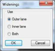
Advanced: This option has been designed for those components that require additional configuration and it can now only be used for the configuration of the additional width application point. Upon selecting the Additional widths option and pressing this button the following window will appear in which we will indicate the application vector.
Options
This section has a series of options that directly affect the segment and each of its components. For each and every one of them it is necessary that in the segment at least the horizontal alignment, cross-sections, vertical alignments and sections have been imported, meaning, the road can be made up. Below is a description of each option:
Verify: This option analyses the segment and displays an error report indicating the possible defects existing in the section definition. For more details see the section Generate Modified Terrain in the section on Cross-sections.
Check: Use this button to view the final state of our road in elevation plan view in a new window. For more detail see the section Check cross-sections in the section on Cross-sections**.
Volumes report: This will display the volume report of the segment file. This option is described in more detail in Volumes section.
Draw: When this option is selected it will draw the cross-sections. For more detail see the section Draw cross-sections in the section on Cross-sections.
Proposed: This option is used to generate the final modified terrain of the road defined by the segment, and if roadbed layers exist, a modification associated with any of the existing roadbed layers can be generated. For more details, see the subsection Generate Proposed Terrain within the section Cross-Sections.
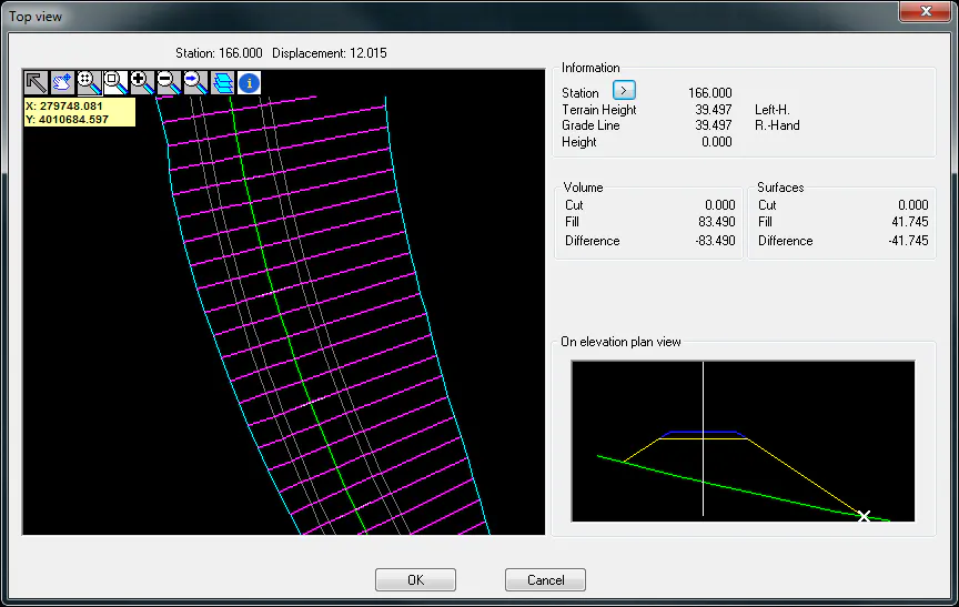
Top view: Use this button to visualize the top view of the complete road that we have defined with the working segment.
Sanitation Fill: If sanitation is defined in the section associated with the segment, this enables exporting the routing section as cross-sections file, which will appear as a black line in the drawing.
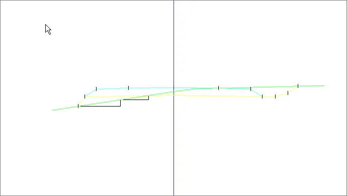
Preview
Graphic representation of the element of the selected segment. Depending on the object selected there are several visualization options. For example, each one of the cuts that comprise a cross-section can be viewed.
Report
Activating this button generates a complete report of the elements linked to the segment. The following window will appear for the purpose of customizing the type of list to be generated.
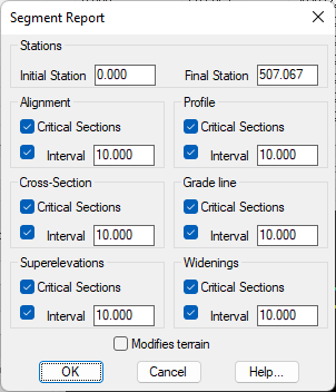
It is possible to indicate the stations for generating the list and for each segment element if we wish to send the information on the unique points or if we want the report with a determined interval.
In the case of Modified Terrain, it will generate a report on the vertical alignment and subgrade cross-sections if roadbed has been assigned to the section.