
tcpMDT
[PRO] Convert Platforms from Drawing - MDT26

Convert Platforms from Drawing
 | Command to execute in the CAD |
|---|---|
Vertical menu | MDT26 > Templates > Convert Platforms from Drawing |
Ribbon menu | Templates > Create > Convert Drawing |
Command line |
This command is used to build a complete platform assignment of a particular road from a drawing in top view.
The program will build the template file, where it will include all the platforms necessary to build the road. It works well in 2D or 3D.
This drawing in top view must be built from AutoCAD polylines or lines.
Additionally, the command Assign properties to platform vectors can be used to associate properties with polylines to simulate curbs for instance, and through which two or more vectors may be associated with the polylines of interest. This command is explained in more detail further on. To use it, if we select polylines "with properties", the command will automatically create the corresponding vectors in the construction of the platform.
When the command is executed, the program will first request the horizontal alignment to work with. Then the following dialog box is displayed with the elements described below.
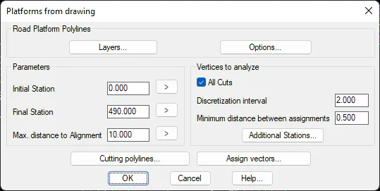
Layers: For selecting the layer or list of layers where the entities are located that will be forming part of the element in question.
Options: Particular configuration characteristics.
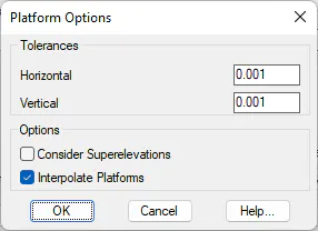
Horizontal Tolerance: Minimum horizontal distance that can exist between two platform vertices.
Vertical Tolerance: Minimum vertical distance that can exist between two consecutive platform vectors.
Consider Superelevations: When this option is checked the platform, vectors are configured as superelevations.
Interpolate Platforms: If this option is checked the program will apply the option to interpolate the platform, deleting all unnecessary intermediary platforms.
Initial station: Station from which the template is to be generated.
Final station: Station up to which the template is to be generated.
Max. distance. to Alignment: In this parameter we indicate the maximum distance to the horizontal alignment in which the program will find the entities for building the template. In this case, it will analyze 10 meters to the left and right of the horizontal alignment.
Vertices to be Represented
All Cuts: Activating this box orders the program to analyze all the vertices of the designated polylines.
Discretization Interval: The program will analyze the drawing with the interval on the axis specified in this option.
Minimum distance between assignments: Once all the intersections have been processed the program will optimize the set of platform assignments conducted in such a way that there are never two consecutive assignments with a distance between them less than that specified in this box.
Cut Polylines: Clicking on this tab will enable us to select a set of polylines which will delimit the end of the polyline. The purpose of this option is for the case of circular regions in which platforms from different stations can be overlapped.
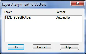
Assignment of Vectors
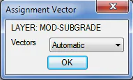
This window is used to inform the program what type of platform vector is to be used for each of the layers selected. In the event of selecting the default option (Automatic) the program will assign a code automatically.
 |  |
|---|---|