
tcpMDT
[PRO] Create - Edit - MDT26
Create/Edit
 | Command to execute in the CAD |
|---|---|
Vertical menu | MDT26 > Templates > Create/Edit |
Ribbon menu | Templates > Create > Create/Edit |
Command line |
Este comando define la plantilla completa. Al ejecutarlo, el programa solicita un archivo, que puede ser una plantilla o un archivo de segmento.
If a template file is selected, you can specify a new file or modify an existing one.
Selecting a new template file opens a window to indicate the template type: urban or road (with or without median).
Modifications made during the initial template type definition can be changed later.
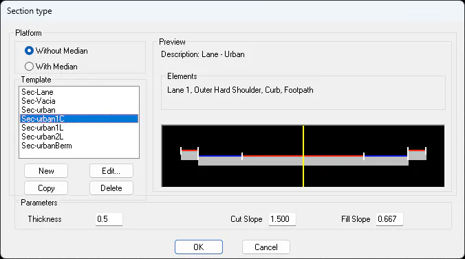
Each template type offers default templates as a base for section development. Even after selection, you can modify them by adding or removing vectors or changing properties.
You can also define new templates according to your needs, available for new section definitions.
The following buttons customize sections:
New: Create a new section by specifying its name and an optional description.
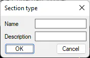
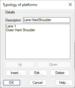
Edit: Editing the selected template opens a window to define each vector. Only one side is defined; consider all vectors that will be used on the platform. Not al Create a new section. Indicate the name of the section and give a brief description (optional).
Edit: When editing the template selected in the list the following window will appear for defining each of its vectors. Only one of the sides is defined, so that in the definition it is necessary to keep in mind all the possible vectors that will be used in the platform. In a later definition not all the vectors have to be used on both sides.
Distinct properties may be assigned to each of the vectors, from the type of vector to whether it can be superelevated or not. All the characteristics can be modified in the definition of the template.
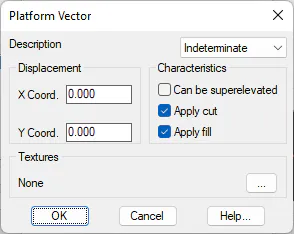
Description: Type or name of the vector.
Displacement: The dimension the vector will have by default.
Texture: Type of texture to be applied to the vector for later visualization with textures.
Can be superelevated: Indicates whether the vector can be superelevated by default.
Apply cut/fill: The possibility to indicate at which part of the section to apply the vector, when it is cut, fill or both.
Copy: Copy an already-existing template by changing its name. This option is of enormous use in cases when the new section is very similar to one that already exists and prevents having to give the definition for all the vectors.
Delete: Deletes the selected section.
Template Parameters
Roadbed Thickness: Thickness to be assigned to the roadbed that is assigned by default.
Slope Cut: Cut slope that is assigned by default to the new section to be defined.
Fill Slope: Fill slope that is assigned by default to the new section to be defined.
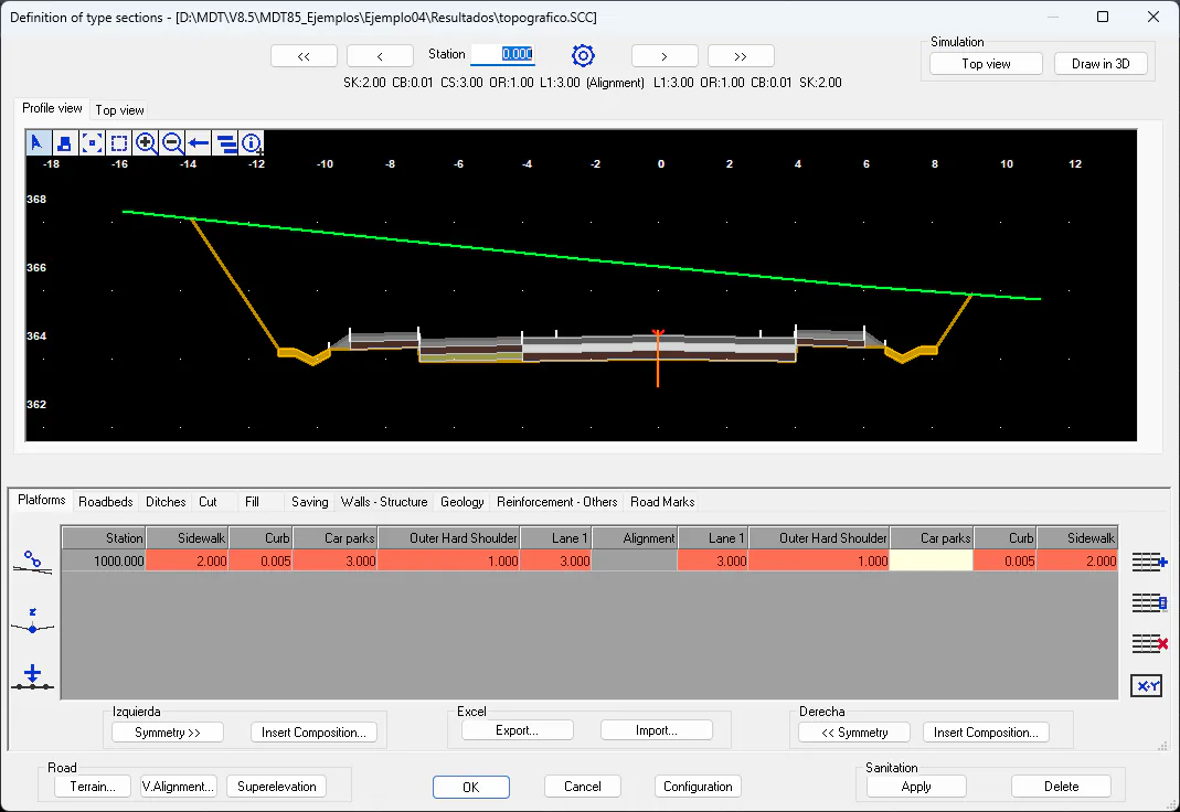
Once the template is defined or the file in which we will be developing our template is selected, the following window will be displayed for defining all the construction elements of the template section and the station where each one is located.
By default, up to the final station, the selected platform template as well as the roadbed, fill slope and cut slope specified in the previous dialog will be assigned.
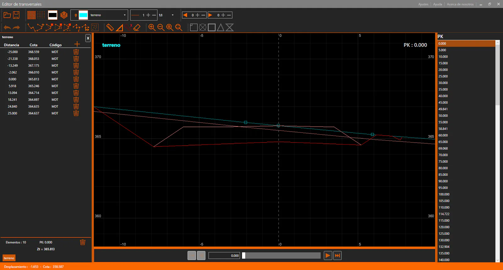
Road. Terrain: This button will open an editor displaying the cross-section and the natural ground surface. The profile can be modified either graphically or through the table shown on the left. The cross-section construction will be updated automatically according to its definition.
Road. Vertical Alignment: This button displays the list of vertical alignments associated with the roadway. Any modification made to the alignment will automatically affect the composition of the typical cross-section.
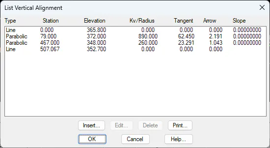
This option is described in greater detail under Vertical Alignments > List
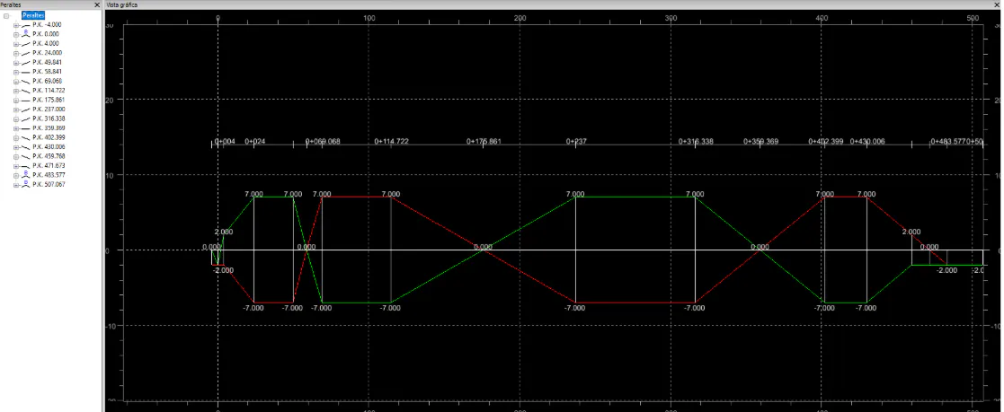
Road. Superelevation: Pressing this button provides access to the superelevation definition associated with the roadway, if any has been assigned. Any modification made in this editor will be automatically reflected in the definition of the typical cross-section.
Sanitation. Apply.
This option allows the embankment undercut treatment to be defined for a previously defined roadway. Pressing this button generates the entire roadway and opens a window for configuring this property.
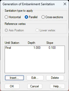
Type: Specifies whether the undercut treatment is constructed horizontally, parallel to the roadway, or based on specified cross-sections.
Reference vertex: Reference point considered for defining the undercut depth, which may be either the Centerline Position or the Lowest Elevation Vertex.
The list defines the undercut behavior up to a specified chainage (station). For each interval, the undercut depth and the side slopes connecting to the natural ground are specified.
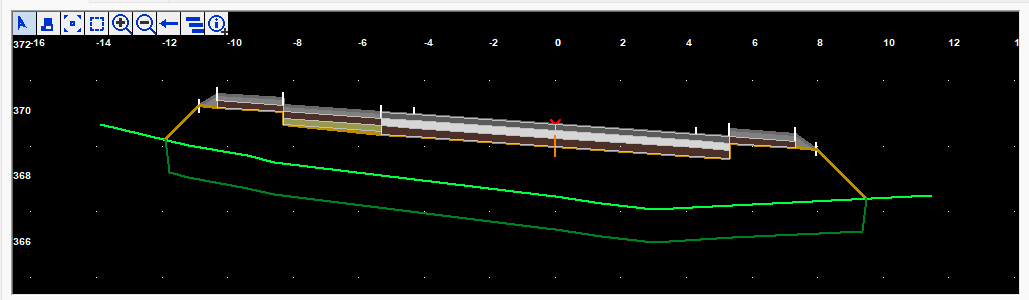
There are three different sections in this window:
Top
Buttons for displacement over the course of each of the stations, in the case of selecting a template file, if no information exists on the natural terrain the button  is available which simulates the cross-sections in order to obtain a real simulation of the section.
Pressing the button displays the following window which is described below:
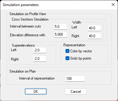
Cross Sections Simulation: Here we establish the parameters for creating the virtual cross-section that will form part of the template.
Interval between cuts: Interval with which the profiles are developed.
Elevation difference with grade: To establish the elevation difference with the grade, basically for the simulation of slopes.
Left Width: Cut width of the left cross sections.
Right Width: Cut width of the right cross sections.
Superelevations: To simulate the superelevations, establish the values both to the left and the right.
Ground Simulation: In this section you can configure the interval of ground representation, using the current station as a reference, in this way, if you set the value to 200 and you are in station 300, the ground section from the station 100 to 500 will be shown.
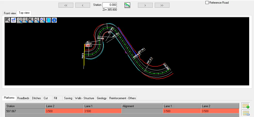
Ground view can be accessed from the Top view tab.
Middle
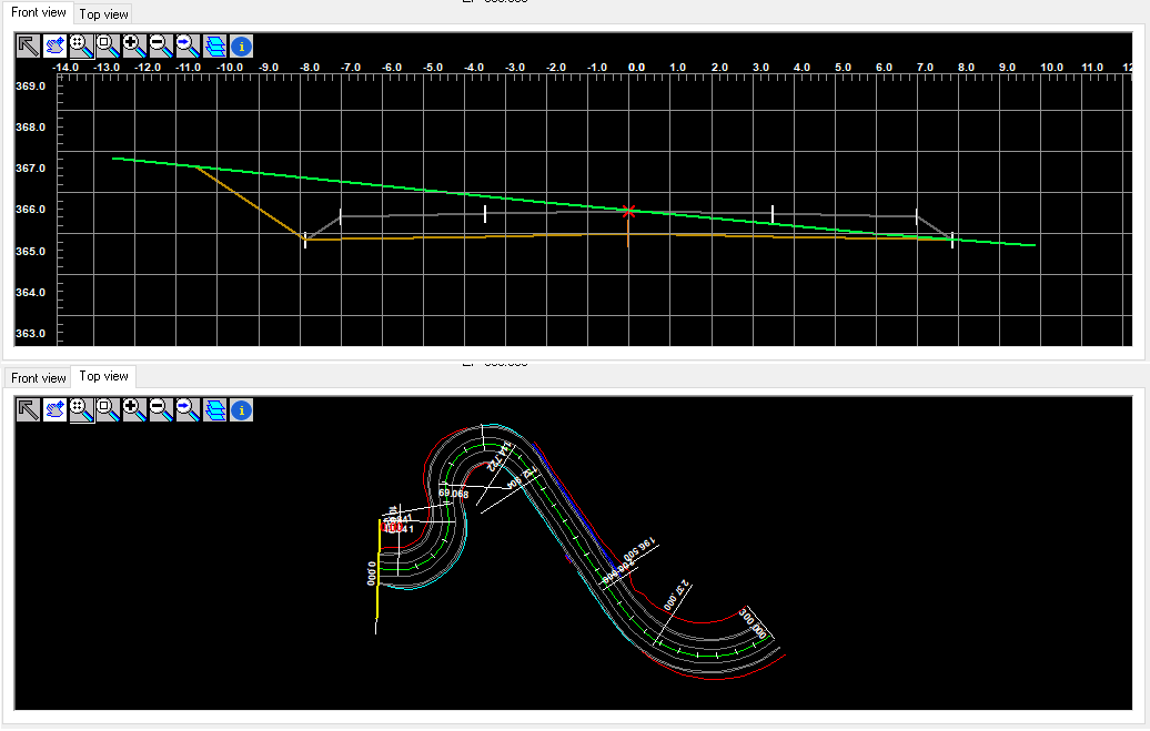
The drawing of the section being defined is in this part of the widow. The drawing changes in real time according to the different modifications made.
On the top right of the drawing there is a series of zooming tools to visualize the section in more detail.

On the top toolbar, if we click the  icon and graphically select one of the section's vectors, the program displays information on its definition.
Additionally, you have two points of view, Front view and Top view.
Bottom
Each of the elements comprising the section is defined in this part of the window. It features a series of tabs for quicker access to their definitions.
The definition is done by station, indicating by lines up to which station each element is defined.
Once an assignment has been made, it is possible to change the station previously entered, either by clicking on the station box and entering the value or double-clicking on the same box and thus designating the station graphically.
In turn, each element to define has a series of buttons for typical tasks such as inserting, editing, deleting, etc.
There is also the bottom middle button Top View which allows us to visualize a top view of the state of the section we are defining.
Below is a detailed description of the definition of each element:
Platform
A platform is defined as the set of vectors formed on both sides of the horizontal alignment, or from the median if there is one.
This set of vectors also configures the subgrade or surface supporting the roadbed. In other words, it will be used to calculate the excavation surface area. The ditch and/or the slopes will be situated at the ends of the platform should there be a cutting or fill surface.
If superelevations are considered, they will be applied to the vectors selected. For this purpose, they can be marked by double clicking on the graphic representation or changing the corresponding vertex's properties. They are clearly differentiated in the dialog box, because the vectors that can be superelevated are displayed in red, while the rest are displayed in white.
Additionally, defining the pivot element is essential, as it is at this vertex that grade line height will be applied and from where the superelevations are applied to both sides. The pivot vertex is represented in the image with a red arrow. For platforms with a median, two pivot points exist one for each roadway.
The data is introduced into a series of cells with the name of the vector in the top row, having previously been defined in the template. The first column is the station up to which the corresponding platform is applied.
The X displacement of the vector in question can be directly introduced in the cells. To apply a displacement in Y, double clicking on the desired cell a window appears for modifying this parameter as well as other characteristics.
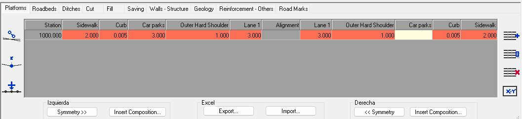
If a cell is left blank, it is assumed that no vector exists for it, so that if in the previous or following definition one does exist, the vector will be automatically interpolated.
As previously mentioned, double clicking on any data cell displays a new window where the characteristics of the selected vector can be configured in more detail.
This window will be different depending on whether we edit a platform vector (Lane, Shoulder or Berm) or another type of auxiliary vector.
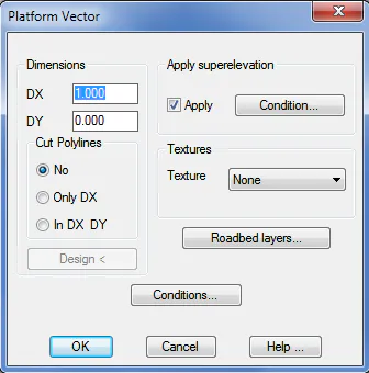
When editing a platform vector, the following window will appear:
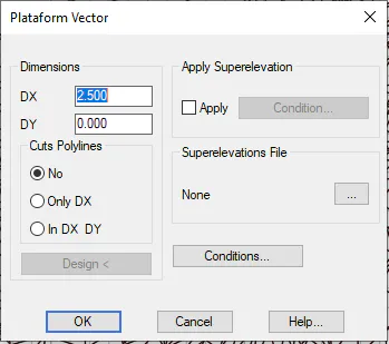
DX: Horizontal vector displacement.
DY: Vertical vector displacement.
Slope: This option will allow us to enter a slope value for the vector and automatically calculate the DY value. Likewise, if we change the DY value, if it will automatically calculate the slope. The DX value will always remain unchanged.
Referring to Polyline: Option to designate a polyline on the ground to which the edited vector is stretched, if there is no intersection, it will take the default assigned value as the width of the vector.
Only DX: Only stretches in X.
In DX and DY: stretches in X and Y (Elevation).
Texture: Optionally set the texture associated to each of the vectors. This option is used to give a more realistic appearance to the 3D representation commands available in the Maps option. If textures are not assigned, the program will automatically assign a texture when the above-mentioned commands are executed.
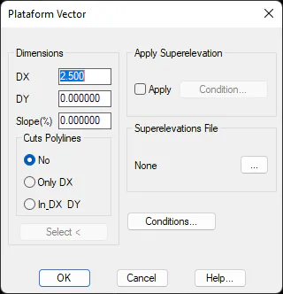
Apply superelevation: Indicate whether the vector can be superelevated. Click on the Condition button to customize the superelevation to apply.
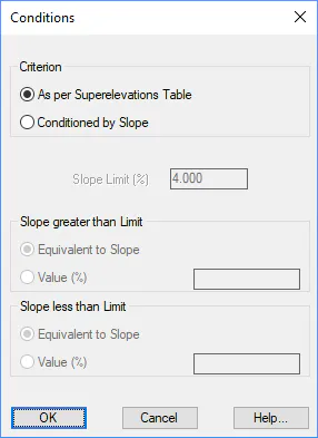
The superelevation will either be applied As per Superelevations Table or Conditioned by Slope. In the latter case, there are two criteria for the application of said slope: it can be either greater than or less than the limit set. There are two criteria for both alternatives:
Equivalent to Slope.
A % value entered by the user (Value box).
Application conditions: A series of conditions can also be applied to the vector according to which it will or will not be defined in the template.
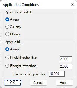
Apply at cut and fill: This is to indicate whether the vector is applied according to whether it is cut only or fill only. Deciding on the vector application is the point of connection for the vector in the corresponding platform.
Also, if deciding that the vector is only applied to fill, there are three options:
Apply Always.
Apply if the height in regard to the previous vector is higher than a value entered.
Apply if the height in regard to the previous vector is lower than a value entered.
Selecting any of the names of the existing vectors and clicking the right mouse button displays a submenu with the following options:
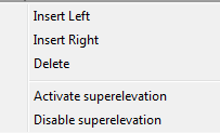
Insert Left: Insert a new vector to the left of the selection, in this case a new window will appear with the vectors available to insert in this position.
Insert Right: The same as for the previous case, only this time the right vector is selected.
Delete: Eliminates the vector selected, completely eliminating the column selected.
Activate superelevation: Activates the superelevation in the vector selected, for all definitions at every station.
Disable superelevation: Similar to the previous only in this case it disables the superelevation in all the stations of the vector in question.
In the event that we select an auxiliary or non-platform vector, the following window will appear, in which the characteristics are similar to those of platform vectors, the difference being that a different superelevation can be applied to each vector.
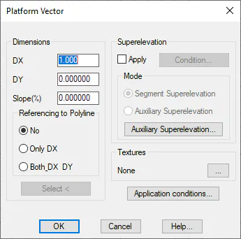
Checking the Apply box under Superelevation will enable the Application Mode option.
Mode of Application:
Segment Superelevation: The superelevation imported to the segment will be used as a reference for the vector being edited.
Auxiliary superelevation: Selecting this option will enable us to select a superelevation file. This superelevation file will be used as a reference to calculate the superelevation of the vector being edited.
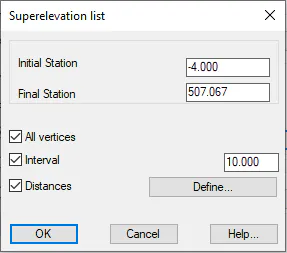
Auxiliary superelevation editing: If the Auxiliary superelevation option has been selected, clicking on this button will enable us to make a list of the superelevation in question. This is described in greater detail in the List of Superelevations command in the Roads/Segments module.
If, on the contrary, we select a group of cells belonging to the same type of vector and click on the right tab, the following sub-menu will appear:
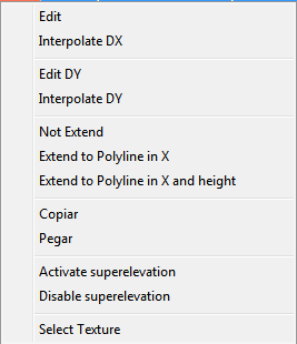
Edit: Edits the vector selected. The same as double clicking on the box to be changed.
Interpolate DX: The option of interpolating the vector or vectors selected between two values specified by the user.
Edit DY: Enables us to assign the same DY to all the vectors selected.
Interpolate DY: In this case, we assign a DY to the first vector selected and another DY to the last vector selected; the DY arising from the interpolation is assigned to the intermediate vectors selected.
Not Extend: Deactivate the option for extending the vector specifying a pre-selected polyline.
Extend to Polyline in X: This option enables us to extend the vector selected to a polyline specified by the user; in this case it will only be extended in X.
Extend to Polyline in X and height: This is similar to the previous option only in this case the extension also applies to the height. The selected polyline should be in 3D in this case.
Copy: Copies the cell selected to the memory.
Paste: Enables us to copy the data from the cells selected from the copied cell using the previous command.
Activate Superelevation: Activates superelevation in the vectors selected.
Deactivate Superelevation: Deactivates superelevation in the vectors selected.
Select Texture: Enables us to assign a specific texture to the vectors selected.
For definitions of templates that have a median, the same properties of the median-type vector can be assigned to it. By double-clicking on the corresponding vector, the following window is displayed for setting up the configuration.
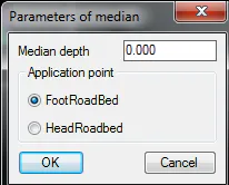
Median depth: Average depth of the median from the pivot point to both sides of the section.
Application point: Indicate here if the roadbed vectors connect at the crown or foot of the roadbed.
Additionally, there are four buttons for carrying out the following operations on the platform definition across the stations.

This inserts a new platform assignment in a particular station. When the button is pressed it will request the station and once it is validated a line is inserted in the position where the vectors are assigned the values of the section with which the template was initially defined. Additionally, you can designate the station graphically in the drawing.

With one of the platforms assigned to a specific selected station, this button makes a copy of the vectors at that station.

Deletes the assignment of a particular station.

With this button we will define the point of application of the grade level. To do this, we first select the name of the vector on which we want to apply the grade level and then select this button.
This option will allow us to define a section in which the grade does not necessarily have to go along the alignment, but, for example, by a curb vector.
The application point is shown with a red arrow in the vertex in question.
Platform pivot without median
Platform pivot with median
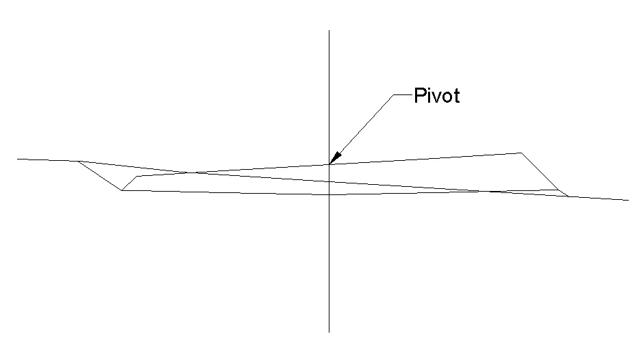
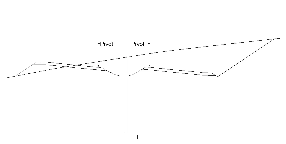

With this button we define the pivot point of the platform, i.e. the point from which the superelevation will be applied to the left and right. To do this, we first select the name of the vector on which we want to place the pivot and then select this button.
In the drawing, the point of application can be seen by a red blade that exists at the vertex in question.

With this button the program allows all the vertices of any polyline to be read, creating a new platform with its vectors.
First, the platform definition window disappears momentarily, to request the designation of a Polyline by placing the cursor on it. Then the Vertex corresponding to the Horizontal Alignment is selected. This is also done with the cursor; on the vertex we want considered as the horizontal alignment of the polygon.
The program will calculate the increases of the vectors drawn in their values (X and Y), with (0, 0) as a horizontal alignment of reference and restoring the dialog box for platform definition.

When this button is pressed in each roadway platform assignment cell, the DX and DY values are displayed. The user may edit them directly within the cell by entering the values separated by a comma.
>> Symmetry : Pressing this button will copy all vectors from the left side to the right side, with all their properties and characteristics.
<< symmetry: Pressing this button will copy all vectors from the right side to the left side, with all their properties and characteristics.
These symmetry options are interesting because if we have a symmetrical platform, it would be enough to define the behavior of the platform on one side of the axis and then apply the symmetry to the corresponding side.
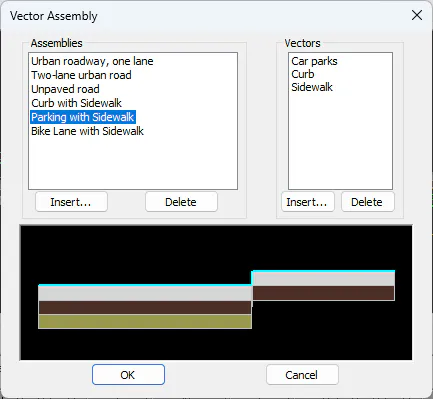
Insert Composition: This option allows the insertion of a previously configured vector composition. TcpMDT includes a set of default compositions for user convenience.
The composition will be inserted on the corresponding side and according to the order defined for the roadway platform vectors.
Export / Import to Spreadsheet
These two buttons will allow us to export the information of the vertices to a spreadsheet, make the necessary modifications in it, to later import it again and automatically read the new data entered.
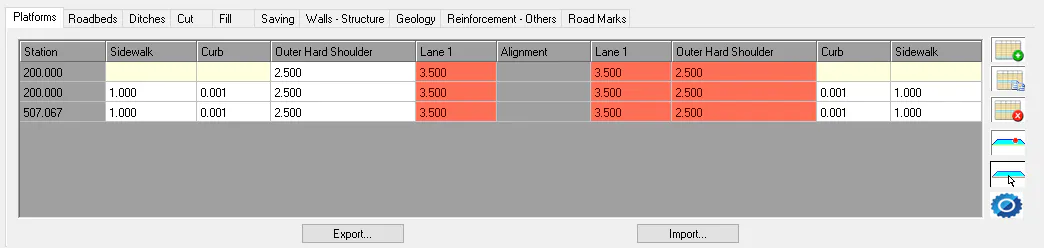
Export: If we export the definition of the previous image, the result would be as follows:

Import: It asks us for the data sheet file (xls, xlsx) and the new information entered is imported, either as a result of adding new lines corresponding to new pks or modifying the characteristics of any vector.
The format for defining the characteristics of vectors is as follows:
Cell value Description
1.5 DX (DY = 0)
1.5;P DX;(DY = 0) Superelevation
1.5;0.3 DX;DY
1.5;0.3;P DX;DY; Superelevation
DX: Horizontal displacement of the vector.
DY: Vertical displacement of the vector.
In addition to the aforementioned tabs for editing the platforms, we have a contextual menu with a series of options described below for each of the vectors of each of the platform assignments.
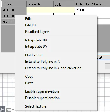
Edit: Edits the properties of the vector selected, similar to double clicking on any of the vectors.
Interpolate DX: We select a series of cells of the same type beforehand. On selecting this option, the program will request the initial DX and the final DX and interpolate the intermediate vectors.
Edit DY: Enables us to edit the displacement in Y of the vector or vectors selected.
Interpolate DY: The same function as the Interpolate DX option; but in this case for the displacement in Y.
Not Extend: Deactivates the option for extending the vector to s polyline when activated.
Extend to Polyline in X: This option enables us to extend the vector to a polyline specified below. It will only be extended in X.
Extend to Polyline in X and height: This is similar to the previous option only in this case the extension also applies to the height.
Activate Superelevation: Activates superelevation in the vectors selected.
Deactivate Superelevation: Deactivates superelevation in the vectors selected.
Select Texture: Enables us to assign a specific texture to the vectors selected.
Roadbeds
Roadbed thickness is defined as the existing thickness between the subgrade and the previously defined vertical alignment. It has some internal and external slope values that will cut the platform defined for the template.
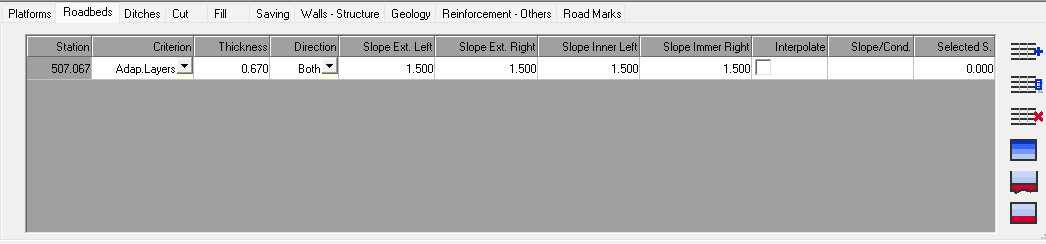
It is assigned by station and at the same time has a series of behavioral characteristics described below:
Criteria: Performance of the subgrade in the definition of roadbed. There are five performance types:
Parallel: The subgrade is always parallel to the platform.

Conditioned: The subgrade will take the maximum value from the value introduced in the box Pend / Cond.
Parallel-Conditioned: The subgrade will be parallel except in other vector types such as lane vectors, to which a slope will be applied via the Pend/Cond. box.
Slope: Subgrade has a slope value determined by the box Pend./ Cond.

Variable: This situation is for those cases in which the subgrade performs independently to the platform, without performing in any of the previously-defined ways. For this, once it is selected the following window is displayed to define subgrade platform vector.
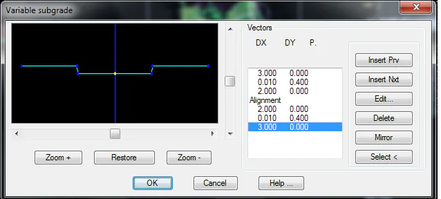
On the left is a graphic representation and on the right is the vector definition with the corresponding buttons for editing. Among these buttons are the typical buttons to insert, edit, and delete, as well as the following buttons:
Mirror: If the platform is the same on both sides of the horizontal alignment. Define only one of the sides and click this button.
Select: If the platform is previously drawn in real dimensions in CAD, this option can be used to graphically select it and, in this way, it will read it and automatically build a list of vectors.
Adapt layers: On selecting this option the subgrade will be defined in accordance with the roadbed layers defined for each of the vectors in the platform. In the event a vector has no associated roadbed layers, the roadbed thickness shall be that defined in the respective definition of the same.
Thickness: Absolute value of measurement to apply under the definitive vertical alignment of the platform. It must be higher or the same as the sum of the layer thicknesses. Any change to this box will immediately modify the graphic image above in proportion to the other data.
Direction: Indicate whether to always apply, whether the section is cut or fill. The decision point to indicate whether the section is cut or fill is the horizontal alignment position.
Slope E.L.: Value of exterior left roadbed slope.
Slope E.R..: Value of exterior right roadbed slope
Slope I.L.: Value of interior left roadbed slope, this is only applicable in the case of templates with a median.
Slope I.R.: Value of interior right roadbed slope, similarly only applicable to templates with a median.
Interpolate: If this is activated it will interpolate the roadbed thickness between the station in question and the station assigned previously to intermediate stations.
Selected soil: The thickness of the soil selected existing under the subgrade. If this value is edited the following window is displayed to configure the parameters of the soil selected.
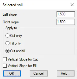
Left Slope: Left slope value of the soil selected.
Right Slope: Right slope value of the soil selected.
Apply to: Indicate whether to apply when the roadbed is cut, fill or in both circumstances.
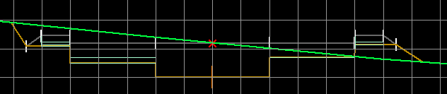
Below is an example of the soil selected in which the slope is different to the roadbed.
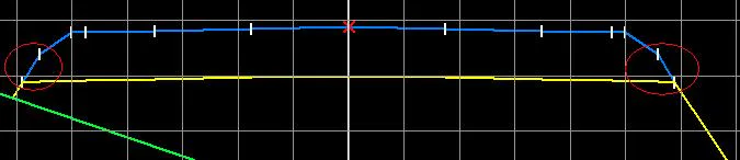
Vertical cut slopes: If this box is activated, the slope of the selected soil in the cut situation will be built vertically until it reaches the slope of the roadbed.
Vertical fill slopes: If this box is activated, the slope of the selected soil in the fill situation will be built vertically until it reaches the slope of the roadbed.
Functions of the different buttons on the roadbed definition panel:

Insert a new roadbed assignment in a particular station. You can designate the station graphically in the drawing.

Copies a roadbed to another station. Copies all the characteristics including the roadbed layers.

Delete the roadbed selected.

Edits the definition of the subgrade. This tab only works if the Variable criterion has been selected.

Directly accesses the Selected Soil configuration explained above.
Roadbeds

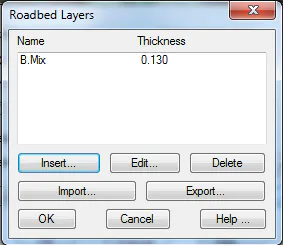
If you press this button, you can define the roadbed layers associated with the selected roadbed. The definition of these roadbed layers only affects the lane, roadside and shoulder type vectors.
When defining a new set of roadbed layers, if you have selected Spanish Regulations, the program will show the Roadbed Catalogue. In this way you can select the one that adapts to the road that you are going to define.
In the editing window you can make all the modifications that you need although the program will notify you in the event that regulations are not complied with.
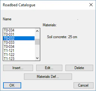
Once the regulations have been selected, the following window will appear where you will configure the different roadbed layers for your road.
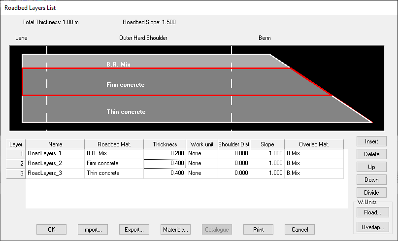
The Roadbed layers are defined from the surface to the contact point with the subgrade. There are different ways of handling and managing the dialog box. It is possible to Import, *Export and Print* the detailed characteristics of each of them.
The top of the dialog box shows the total Roadbed Thickness and the value of the Exterior Slope.
Each layer has an associated customizable Name by the user, this name is the one that will be reflected in the export to the IFC format. See BIM chapter.
The list is entirely editable, so that the properties of each roadbed layer can be directly modified, and their order changed, any of them can be deleted and new ones created. The buttons: Up, Down, Delete and Insert are used for this.
Roadway Surface Material. Material assigned to the roadbed's surface up to the external shoulder.
Thickness: Thickness of the roadbed layer. The sum of all the roadbed layer thicknesses can be no greater than total roadbed thickness.
Shoulder Dist.: Length of the overlap in the layer being defined. It is applied to the layer depending on the overlap selected.
Divide: If one of the materials assigned to one of the pavement layers is "Mixture B", clicking on this button will automatically subdivide it into the following three materials, distributing the thickness equally between each of them:
B.B. mixture.
B.I. mixture.
B.R. mixture.
Roadbeds Overlap
For each of the roadbeds there is the possibility of assigning a different overlap material to the material of the layer in question. You can set a different Overlap configuration left and right. The overlap shall only apply to the Outer Shoulder and Berm vectors.
When you click on the cell corresponding to the overlap, the following window will appear:
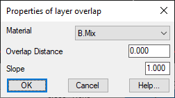
Material: Material that is applied in the overlap area.
Overlap Distance: This value corresponds to the distance that the material is introduced from the main layer into the overlap zone.
Slope: Value of the overlap slope.
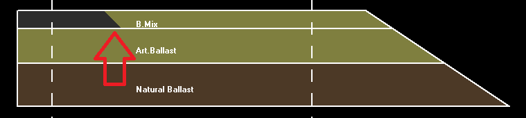
In the next capture you can see a 1 meter overlap on the first layer with a slope of 0.5.
Works Units
This option will enable us to assign different works units to the defined pavement layers. We will then be able to use the Quantity take off > Works Units command to generate different types of reports.
We can assign works units to both the main material and the overlap material for each pavement layer.
Roadway: By clicking on this button, we will assign the works units to the main material of the selected pavement layer.
Overlap: By clicking on this button, we will assign the works units to the overlap material of the selected pavement layer.
The following window will appear for both the Roadway and Overlap options, illustrated in the table below.
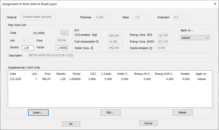
Works Unit. Main.
Assignment of the main works unit. Clicking on the (...) button will display the following window containing the different works units available in accordance with the BC3 database selected (see Settings > BIM). We select the works unit to assign to the selected pavement material.
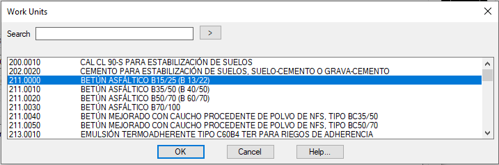
Once selected, the main window will be automatically filled as illustrated in the screenshot above. Moreover, if this works unit had an assigned life cycle unit, it will be filled in automatically.
This main unit can be assigned to five possible measurements:
Volume
Upper area
Lower area
Length
Unit
Complementary Works Units
There is the possibility of assigning several complementary works units to the material of a certain layer. These assignments are managed using the "Insert", "Edit" and "Delete" buttons.
On selecting the Insert or Edit option, the dialogue box illustrated below will appear in which to select the works unit to be assigned.
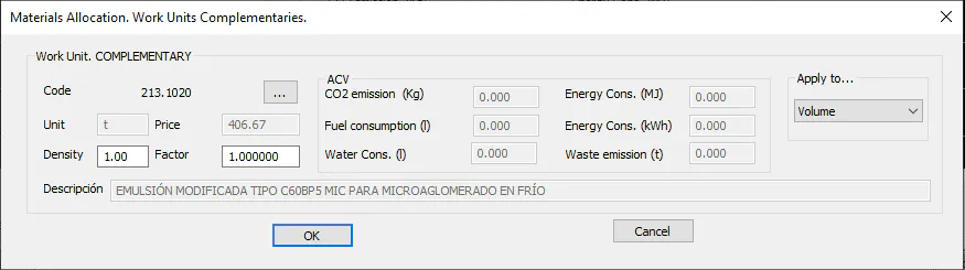
This dialogue box is similar to that of the main works unit, using the (...) button to select the works unit and selecting the application point under Apply to.
The list of complementary works units will be automatically updated once the box is checked.
We have the following sections for the list of assignments
Slope: Slope of the existing overlap in the layer that is being defined.
Overlap Material. Material assigned to the roadbed layer making up the previously defined overlap.
Define Materials: Definition of the materials comprising the roadbed layers.
Additionally, different roadbed layers can be assigned to the vectors that are not templates for lanes, hard shoulders or berms.
To carry out this definition when editing the vector properties, a window is displayed in which by pressing the button Roadbed Layers we can specify the characteristics of each of the roadbed layers for the vector in question.
 |  |
|---|---|
Ditches
A Ditch is defined as the element added to the external edge of the platform. It is configured by adding vectors formed in a positive X direction to vectors given by coordinates associated to the origin or previous point. They move forward if they are positive (x) values. Ordinate increments (y) will be positive upwards and negative downwards.
To the left the data for the ditch is introduced in the corresponding station and on the right is a preview of the ditch that is currently assigned.
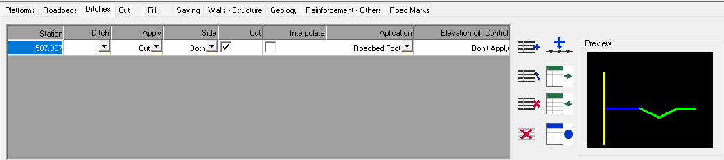
Ditches: Number of the ditch assigned. All the available ditches are listed in the drop-down menu.
Apply: Indicate here whether the ditch is applied to cutting or fill.
Side: Side of the ditch's application.
Cut: If this box is checked, and if the terrain cuts the ditch, it will be cut at this point.
Interpolate: If this box is checked the ditch will be interpolated between the current and the next one assigned.
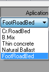
Application: The point of connection of the ditch, at the crown or foot of the roadbed. If we have defined the roadbed layers, this would give us the possibility of placing the ditch in a specific roadbed layer.
Control of Differences in Elevation: This parameter will enable us to monitor whether the ditch has been inserted in accordance with the difference in height in relation to the natural terrain at the point where the ditch is inserted.
The value will be set to "Always" by default, or in other words the insertion of the ditch will not depend on the difference in height between the vertical alignment and the terrain.
Additionally, there are buttons with the functions described below.

This inserts a new ditch assignment. When the button is pressed the window below will appear for defining the ditch with which we wish to work.
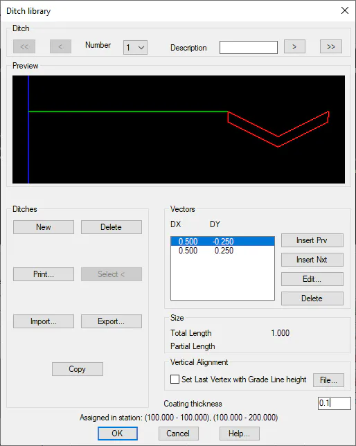
There are three areas:
Ditch: Buttons for moving forward and back over the course of the defined ditch library.
Ditches: Group of buttons for defining or deleting the existing ditches.
New: Creates a new ditch.
Delete: Deletes the current ditch.
Print: Prints the list of ditches with their vectors.
Select: This is used to graphically select a ditch which was previously drawn with an AutoCAD polyline.
Import: Imports ditches from a file.
Export: Exports ditches to a file.
Copy: Copies the current ditch to create a new ditch.
Vectors: The group of vectors comprising the ditch, with the corresponding buttons to insert, edit, or delete them.
By selecting any of the editing buttons (Insert Prv., *Insert Next, Edit* ) the following window is displayed to specify the X and Y displacement that the ditch vector being edited will have.
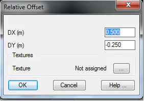
It is important to highlight that the value of the X increment cannot be zero or negative. In other words, vectors always have to travel away from the horizontal alignment. Should a vertical jump need to be entered, a small value can be entered (such as 0.01 or 0.001), which will have practically no effect on the calculations.
In the Textures section the texture associated to each of the vectors can optionally be set. This option is used to give a more realistic appearance to the 3D representation commands available in the Maps option. If textures are not assigned, the program will automatically apply a texture when the above-mentioned commands are executed.
Once the dialog box has been validated, the list defining the current ditch will be updated.
When the ditch to be assigned is selected, a window appears for indicating the station up to which said ditch is to be assigned.

Edit the ditch selected. The same window as in the "Insert" option will appear.

Deletes the ditch assignment selected.

Removes all ditch assignments made.

Gives the option to graphically select a ditch that has been previously drawn with a polyline in real dimensions.
The last vertex at grade line height: the option of extending / removing the last vector of the ditch at the grade line height. The grade line should be selected beforehand using the "File" tab.
For the insertion or editing operation, as well as selecting the ditch, we must indicate the Station at which said ditch would be assigned and with this in mind, once the ditch has been selected the following window will appear.
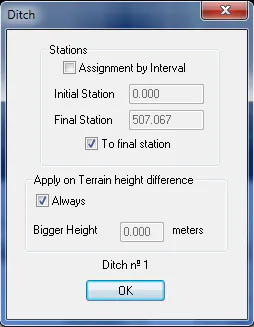
We can carry out the assignment up to a specific Station or between a certain Station interval. With this in mind, we disable or enable the "Assignment by Interval" box. In both cases you have the option to designate stations graphically.
In addition, we will use this window to indicate whether the ditch is always to be inserted or whether this will depend on the difference in height between the point of the ditch and the natural terrain.
Coating thickness: Possibility to apply a thickness to the defined ditch. This thickness will be reflected both in the drawing of the vial and in the export to IFC (See BIM chapter).

When this button is pressed, all account assignments are exported to an Excel file, allowing them to be modified and later reimported into the program.

The first row displays the permitted values for each column. The user may delete, insert, or edit assignments as required.

This option allows the import of an Excel file previously created using the template generated by the Export to Excel function.
Cut Slopes
Cutting slopes are defined as the vectors that set the closure of a cross-section template with the terrain. They are applied to the last vertex formed by the ditch or subgrade, providing this vertex has an elevation lower than that of the terrain in abscissa. It is likewise applied to the last subgrade vertex when its height is lower than that of the terrain compared to the same abscissa value.
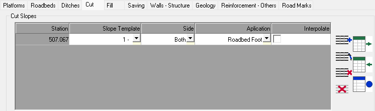
Slope: To select the slope to apply in the current station.
Side: Side of the slope application.
Application: To indicate whether the slope will be connected at the crown or foot of the roadbed.
Interpolate: If this box is checked, in the previous stations where slope is not explicitly assigned it will be interpolated.

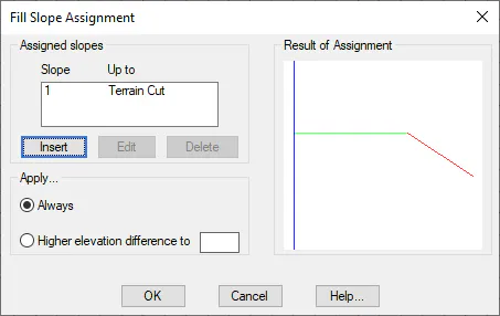
This button is used to insert a new assignment for the cutting slopes. At first the following window will be displayed:
The slopes to be assigned are defined in this window. It is possible to assign up to a maximum of three at the same station, depending on the application point of each.

We use this button to edit the assignment of the designated cutting slope. The following window will appear:
Apply: This parameter will enable us to monitor whether the ditch has been inserted in accordance with the difference in height in relation to the natural terrain at the point where the ditch is inserted.
The value will be set to Always by default, or in other words the insertion of the ditch will not depend on the difference in height between the vertical alignment and the terrain.
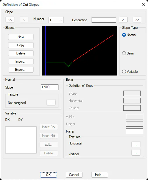
This option is used to define the slopes we are going to assign and there is the possibility of assigning up to a maximum of three in the same station, depending on the point of application of each one.
Assigned Slopes: The slopes are selected with the buttons Insert, Edit and Delete. When Insert or Edit is pressed the following window appears for defining the slope.
The functions for the buttons are described below:
Number: Drop-down list for selecting a slope from the section file.
Description: For writing in text to identify the defined cutting slope. It is not a required parameter but is of enormous use in the assignment of templates as it enables easy identification of each of the assigned slopes.
Delete: Deletes the current slope and automatically goes to the next one, should one exist.
Print: Sends the slope content to the printer.
Copy: Creates a new slope identical to the current slope and assigns it the next number to the last one on the list.
Export: Displays a window containing all the activated slopes ready to be exported so that one of them may be selected.
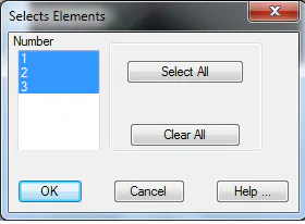
Once validated, the marked slopes are exported to the file that is then requested. The output file is an ASCII file having a .TAL extension.
Import: Imports any .TAL file and adds it to the current slopes. All this information is stored in the section file selected.
New: This creates a Normal type slope by default and assigns it the number following the last on the list. To define different types of slope, proceed as follows.
Under Slope Type there are three possibilities for defining the type of slope to be applied:
Normal Slope
A slope with a single vector. In this field, key in the value resulting from dividing the abscissa (x) and ordinate (y) values making up the slope gradient (tangent) as an absolute value.
A Texture can be applied to it with a view to the road's 3D representation.
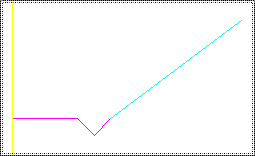
Normal-type slope
Slope with Berm
The slope with berm can be entered by either entering the Slope numerical value or specifying its Horizontal and Vertical values. In any case, when the values of any of them are entered, the rest are recalculated. The following parameters may additionally be specified:
• Height: Height of each of the steps in the berm slope.
• Width: Width of each of the steps in the berm slope.
Split level: Gradient of the horizontal section of the berm slope, the value of which is specified in accordance with the x/y ratio.
A different Texture may be applied to the vertical and horizontal vectors with a view to the road's 3D representation.
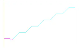
Berm-type slope
Variable Slope
The structure of the slope to be defined is defined by vectors (similar to Definition of Ditch) by entering the dimensions of its respective vectors.
The program indefinitely extends the last vector until it finds natural terrain.
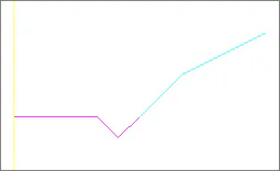
Once the slope to be applied is selected, the following window is displayed to indicate where to apply the slope in question.
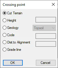
Cut Terrain: The last slope vertex extends until it intersects with natural terrain.
Height: The slope will be extended up to a specific height. This value is applied vertically from the slope's connection point.
Geology: In this case the slope will extend up to the specified geological layer.
Code: For this case the cross-section must be coded, so the slope will stretch to the cross-section vertex with the code specified on the side indicated. In such a case the slope definition is irrelevant as the slope is obtained from the cross-section vertex with the code specified.
Dist. to Horizontal alignment: In this last case a distance to the horizontal alignment is specified and the slope is created from the section connection point up to the point on the natural terrain whose distance to the horizontal alignment is specified in this option. The same as the previous, it is independent of the defined slope as the slope is marked by the value of the distance to the horizontal alignment.
Grade line: In the latter case, a grade line is used as the reference for the extension of the slope, and on selecting this option the program will request the grade line file and will extend the slope in question to the height of the grade line in the corresponding station.

Deletes the selected slope assignment.

Removes all existing cut slope assignments.
When this button is pressed, all cut slope assignments are exported to an Excel file, allowing them to be modified and later reimported into the program.

The first row displays the permitted values for each column. The user may delete, insert, or edit assignments as required.
This option allows the import of an Excel file previously created using the template generated by the Export to Excel function.

Clicking on this option will enable us to assign a works unit to the slope assignment executed. The procedure for managing the works units is similar to that applicable to the Pavement Layers section. Works units can be assigned for each of the slope assignments executed.
We will then have the option of generating the corresponding reports in accordance with the assigned works units using the Measurements options.
For the insertion or editing operation, as well as selecting the current slope, we must indicate the station at which said slope would be assigned and with this in mind, once the cut slope has been selected the following window will appear.
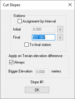
Assignments can be made to a specific station or between a given station interval. To do this, you simply deactivate or activate the Interval Assignment box. Stations can also be designated graphically.
In addition, in this window you can indicate if the slope will always be inserted or if its insertion will depend on the height difference of the application point of the ditch with respect to the natural terrain.
Crowns
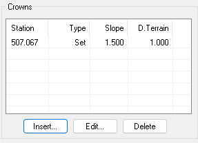
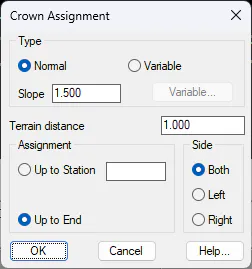
This option gives the possibility to establish a different value to the slope in the final section of contact with the natural terrain, in the case of cutting. Different parameters are available for defining the performance of the crown. The different configuration parameters are described below:
 |  |
|---|---|
Type: Method of defining the crown slope.
Normal: A single slope which will be defined in the slope box.
Variable: Possibility to define a crown slope with several vectors, pressing the "Variable" button will access the definition of it. In the composition of the section, the software will automatically extend the terrain until contact with the terrain.
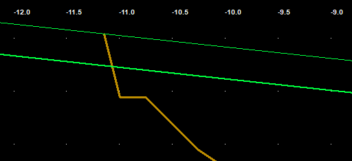
Slope: Slope value in the final section.
Station: Station up to which the specified crown is applied.
Distance to Terrain: Height difference between the terrain and the point of application of the new crown slope.
Side: Side on which the user wishes to apply it.
The defined cutting crown can be visualized in the image below.
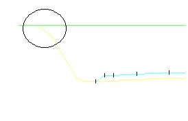
This can also be defined with the definition of the cutting slopes assigned by geological layer, but this way is much simpler and more direct and obtains the same result.
Fill Slopes
Fill slopes are defined as the closure of a cross-section template with the terrain. These are applied to the last vertex making up the ditch or the subgrade, as long as that vertex has a greater height than the terrain in abscissa. They are also applied to the last subgrade vertex when its height is greater than that of the terrain compared with the same abscissa value.
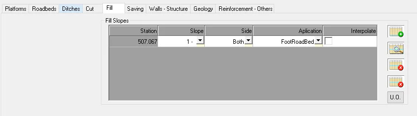
Slope: Selection of the slope to apply in the current station.
Side: Side of the slope application.
Application: Indicate whether the slope will connect at the crown or foot or the roadbed.
Interpolate: If this box is checked in the previous stations that are not explicitly assigned the slope will be interpolated.

This button is used to insert a new fill slope assignment. Initially the following window will be displayed:
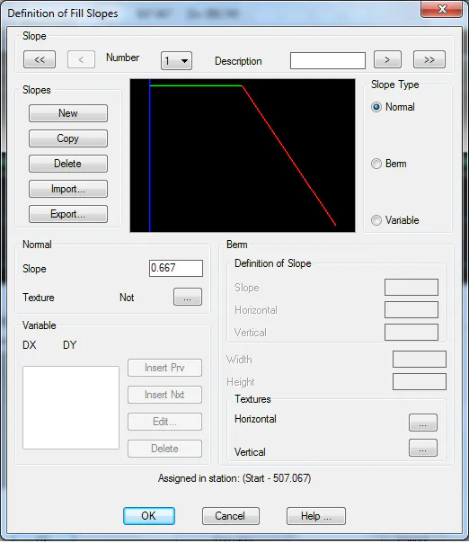
This window is used to define the slopes to be assigned; it is possible to assign up to a maximum of three at the same station, depending on the point of application of each.

Clicking on this tab will enable us to edit the assignment selected in the list. The following window will appear:
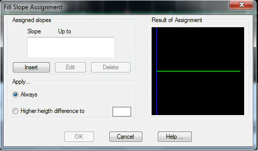
Apply: Specify up to which station the slope or slopes selected are to be applied.
This option is used to define the slopes we are going to assign and there is the possibility of assigning up to a maximum of three in the same station, depending on the point of application of each one.
Assigned Slopes: The buttons Insert, Edit and Delete are used to define slopes. When any of them is clicked the following window will be displayed for defining the slope.
A description of the functions of each button follows:
Number: Drop-down list for selecting a slope from those existing in the section file.
Description: Text for identifying the defined fill slope. It is not a necessary parameter, but it will be of enormous use in the assignment of sections as it makes each slope assigned be easily identified.
Delete: Deletes the current slope and automatically moves to the next slope if one exists.
Print: Sends the slope content to the printer.
Copy: Creates a slope identical to the current one and assigns it the next number following the last on the list.
Export: Displays a window containing all the slopes ready to be exported, so that any of them may be selected.
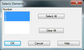
Once validated, the slopes marked are exported to the file that is then requested. The output file is an ASCII file and has a .TAL extension.
Import: Imports any file with a .TAL extension and adds it to the current platforms. All this information is saved in the section file selected.
New: Creates, by default, a Normal-type slope, assigning it the number following the last on the list. To identify different types of slopes, proceed as follows.
Select the Slope Type to define one of the three options for slopes that can be applied.
Normal Slope
Slope with a single vector. In this field, one keys in the value resulting from dividing the abscissa (x) and ordinate (y) values making up the slope gradient (tangent) as an absolute value.
A Texture can be applied to it with a view to the road's 3D
representation.
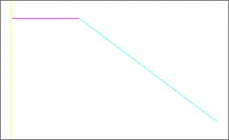
Normal-type Slope
Slope with Berm
The slope with berm can be entered by either entering the Slope's numerical value or specifying its Horizontal and Vertical values. In any case, when the values of any of them are entered, the rest are recalculated. The following parameters may additionally be specified:
• Height: Height of each of the steps in the berm slope.
• Width: Width of each of the steps in the berm slope.
Split level: Gradient of the horizontal section of the berm slope, the value of which is specified in accordance with the x/y ratio.
A different Texture may be applied to the vertical and horizontal vectors with a view to the road's 3D representation.
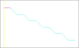
Berm-type slope
Variable Slope
The structure of the slope to be defined is defined by vectors (similar to Definition of Ditch) by entering the dimensions of its respective vectors.
The program indefinitely extends the last vector until it intersects natural terrain.
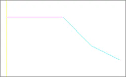
Once the slope to be applied is selected, the following window is displayed to indicate where to apply the slope in question.
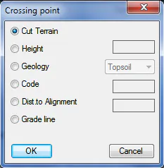
Cut Terrain: The last slope vertex extends until it intersects with natural terrain.
Height: The slope will be extended up to a specific height. This value is applied vertically from the slope's connection point.
Code: For this case the cross-section must be coded, so the slope will stretch to the cross-section vertex with the code specified on the side indicated. In such a case the slope definition is irrelevant as the slope is obtained from the cross-section vertex with the code specified.
Dist. to Alignment: In this last case a distance to the horizontal alignment is specified and the slope is created from the section connection point up to the point on the natural terrain whose distance to the horizontal alignment is that specified in this option. The same as the previous, it is independent of the defined slope as the slope is marked by the value of the distance to the horizontal alignment.
Grade line: In the latter case, a grade line is used as the reference for the extension of the slope, and on selecting this option the program will request the grade line file and will extend the slope in question to the height of the grade line in the corresponding station.

Deletes the selected cutting slope assignment.

Clicking on this option will enable us to assign a works unit to the slope assignment executed. The procedure for managing the works units is similar to that applicable to the Pavement Layers section. Works units can be assigned for each of the slope assignments executed.
We will then have the option of generating the corresponding reports in accordance with the assigned works units using the Measurements options.
For the insertion or editing operation, as well as selecting the current slope, we must indicate the station at which said slope would be assigned and with this in mind, once the fill slope has been selected the following window will appear.
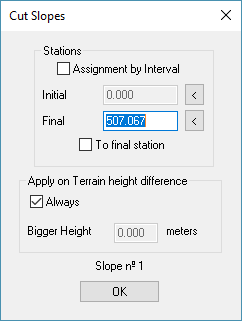
Assignments can be made to a specific station or between a given station interval. To do this, you simply deactivate or activate the "Interval Assignment" box. Stations can also be designated graphically.
In addition, in this window you can indicate if the slope will always be inserted or if its insertion will depend on the height difference of the application point of the ditch with respect to the natural terrain.
When this button is pressed, all fill slope assignments are exported to an Excel file, allowing them to be modified and later reimported into the program.
The first row displays the permitted values for each column. The user may delete, insert, or edit assignments as required.
This option allows the import of an Excel file previously created using the template generated by the Export to Excel function.
Median Element
The term median defines the ditches that are found at the end of the slope intersecting with natural terrain. Generally, these are used to control the water falling down fill or cutting slopes, among other functions.
In this section the central reservation element is also defined referring to the ditch constructed in the median in the case of motorway templates.
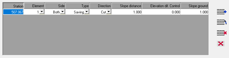
Station: Station up to which the saving or median element is applied.
Side: Side of application.
Type: Indicate here whether the element will behave like a saving ditch or a median element.
The following parameters are only applicable in the case of saving ditches:
Direction: If applied in cutting or fill.
Slope Distance: Point of application of the ditch measured from the slope's contact with the terrain.
Height dif. Control: This parameter is used to control the ditch. If the height difference between the slope ends is greater than this parameter, the corresponding ditch is applied; if it is not, it is not applied. A "zero" value indicates that the saving ditch is always applied.
Closing slope: Once the ditch has been vectorially added to the section, the contact slope of the last vertex of the safeguard ditch with the natural terrain.
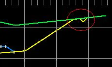
A red circle indicates the saving ditch.

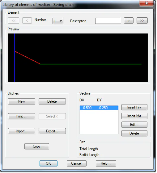
This button is used to insert a new saving ditch or median element assignment. It displays the following window for defining and selecting the ditch to apply.

For editing the ditch element. The same window will appear as that of the "insert" option.

Deletes the saving ditch or median element selected.

Removes all assigned safeguard ditches.
Structure Assignment
Structures are understood to mean the road station intervals that will not have a cross-section template definition. This will be applicable for all later commands that work with this cross-section template, namely for drawing and checking cross-sections, volumes, surface area calculations, etc.
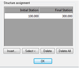
The image is of a defined structure from station 100 to 300 inclusive.
Insert: This introduces a new white line into the list where the initial and final stations are introduced, between which the structure is found.
Select: This option enables the graphic selection on the drawing of the structure's initial and final stations. The station is calculated projecting the point selected onto the working horizontal alignment.
Delete: Deletes the selected structure.
Delete All: Deletes all the defined structures. A warning appears to notify that all assignments will be deleted and may not be recovered.
Assignment of Walls
This defines the vertical cuts in the section. These cuts are totally vertical, starting at the last vector of the section and according to the distance entered. They cut into the natural terrain.
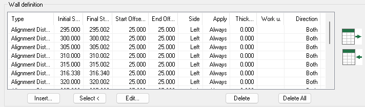
There are two types of walls:
Alignment distance: This wall is defined with a set of stations and the horizontal alignment distance between the initial station and final station, interpolating the stations in between.
Slope Length: This wall is also defined by initial and final stations and is applied if the horizontal slope distance exceeds the Slope Length parameter.
When clicking on the Insert or Edit buttons the following window is displayed, to manage the creation or editing of a wall, the definition of which we then describe.
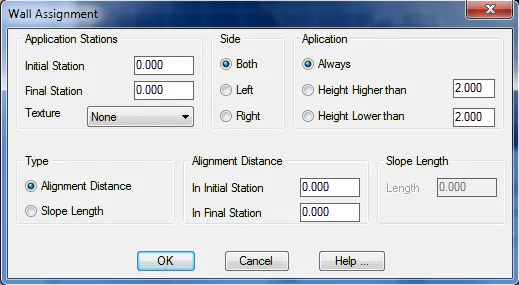
Initial station: Station from which the wall is to be applied.
Final station: Station up to which the wall is to be applied.
Thickness: Assignment of a certain thickness to the wall for its representation.
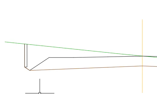
In the case of the alignment distance wall, for every station a Distance must be specified. This value is the relative distance from the horizontal alignment. The program will interpolate between the distance entered at the initial station and the final station for the intermediate stations.
Application: We can specify that the walls are used always or only when the height of the same is greater or less than a value specified by the user.
Length: For the Slope Length wall, this value indicates the maximum horizontal displacement the slope can have before applying the vertical cut.
Texture: Type of texture applied to the wall for its 3D representation.
It is possible to specify whether the wall is applied to the Left, Right, or both sides simultaneously.
Additionally, the following buttons are used for managing and assigning walls.
Select: This option is quite useful as it enables the automatic creation of a wall assignment from the selection of a line or polyline in top view. The program will request all the lines or polylines representing the walls and analyzing them with regard to the project horizontal alignment it will automatically calculate the walls.
Work Unit: Possibility of assigning the work unit to a specific wall assignment. The calculations of the units of works can be viewed from the section of Quantity take off > Work Units command.
Delete: Deletes the assignment of the wall selected.
Delete All: Deletes all existing wall assignments.
When this button is pressed, all assignments of wall are exported to an Excel file, allowing them to be modified and later reimported into the program.
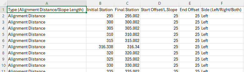
The first row displays the permitted values for each column. The user may delete, insert, or edit assignments as required.
This option allows the import of an Excel file previously created using the template generated by the Export to Excel function.
Definition of Pipes
In this section, enter a previously defined pipe file or create a new one.
Select:Select the pipe configuration file. When you select one, the definition appears in the graphics window.
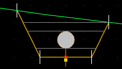
Edit: Allows you to edit the pipe definition characteristics. For more details, see the Pipe Definition in Elevation section.
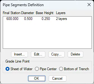
Copy: It allows you to copy the selected assignment to a new pk, copying all its characteristics.
Delete: Deletes the previously created pipe section file assignment.
The specific stations detailing the pipe section's behavior will be automatically added to the platform assignment to display all properties in the section edit.
Geology
The different thicknesses of the geology of the natural terrain are defined in this section. Currently, up to four different strata types are supported:
Org.Soil
Soil
Shale
Rock
For each one there are two options:
Thickness: In this case the parallel layers of land are considered, for this you enter a value in meters that represent the thickness.
Cross section: Option to select a cross section file that represents the terrain in question, whether it's the organic soil, transit or rock.
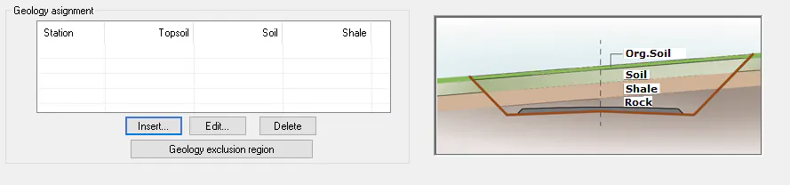
To the right of the panel is a drawing representing the distribution of each strata of terrain.
On the left is the definition of these by station, indicating up to which station it is defined and the thickness of each one:
Insert -- Edit: In both these options, the one for inserting a new element and the other to edit an existing one, the following dialog box appears to specify the terrain characteristics up to a particular station.
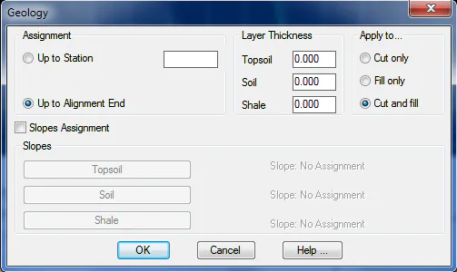
Assignment: This is to specify up to which station we are going to apply the defined geology type.
Layer Thickness: You establish the thicknesses of the different types of terrain that make up the section. As indicated above, a fixed thickness or a cross section file can be indicated.
Layer Thickness: The thickness of the different types of terrain comprising the section are set. This value will be used in the assignment of cutting slopes to specify the type of slope assignment.
Assign Slopes: This option enables us to conduct a rapid assignment of the slope for each of the types of geology defined.
Clicking on the corresponding tab will assign the slope to this layer of terrain. Once the assignment of geology has been completed and the dialog box validated, the corresponding cutting slope will be assigned automatically.
Delete: Deletes the selected assignment.
Geology exclusion region: This option enables us to specify a given area of the cartography affecting our road, at which we do not wish any geology calculation to be conducted.
As such, we need to draw one or more closed polylines in the areas we wish to exclude from the calculation, and once we have drawn these polylines we click on this button and draw the said polylines. The program will automatically consider these regions as areas in which the specified vegetal soil thickness will not be applied.
Clearing Berms
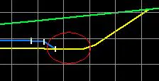
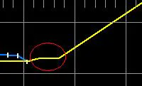
A Clearing Berm is a vector with a determined slope found before a ditch, meaning after the platform, or before the slope inclination. The two types are illustrated in the images below within the red circles.
 |  |
|---|---|
Before the Ditch | Before of Slope |
Below is the window that uses the command to assign the berms to the template.
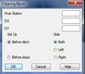
Station: Station up to which the clearing berm is assigned.
DX: X displacement of the vector that represents the clearing berm.
DY: Y displacement of the vector that represents the clearing berm.
Set Up: As indicated previously in the two images, the clearing berm's point of application, whether this is before the ditch or before the slope.
Side: Indicate the side on which to apply the Clearing Berm.
The buttons Insert, Edit and Delete are used to edit the data.
Definition of Reinforcements
In order to calculate surfaces and volumes, MDT can consider roadbed reinforcements. It is necessary that the initial and final vertices of the sections of the cross-section file to be reinforced are coded as Pavement, so that the program can automatically differentiate the part of each profile that should be reinforced. See the Cross-Section Configuration section for further details or the Obtain Cross-Section Profiles command.
Below is a description of each parameter that defines the reinforcement application.
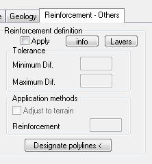
Apply: If this box is checked it indicates that we wish to apply reinforcement.
Layers: This option enables us to assign different roadbed layers to the reinforcement area. If this assignment exists when calculating the volume of roadbed layers, the calculation of the corresponding materials will appear. If there is no assignment of layers, the item "Reinforcement" will appear as material in the calculation.
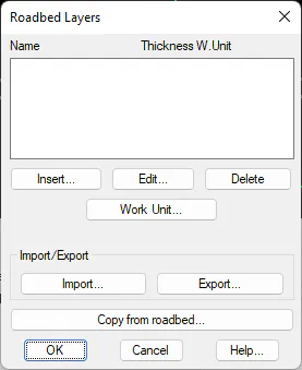
If we press the button Copy from roadbed the firm layers of the last assigned roadbed are read and automatically associated with the Reinforcement.
Tolerances: To apply reinforcement in a particular station the following condition must be met. The height difference in the vertices where the reinforcement is to be applied between the vertical alignment height and the terrain height must be between the Minimum Dif. and Maximum Dif. values.
The objective of these tolerances is to control the application of reinforcement only when the terrain is very near the vertical alignment height.
Application methods: Once it is decided to apply reinforcement to the template, in the area to be reinforced there are two options for the construction of the reinforcement base:
Thickness: Indicate here the thickness of the terrain in the area to be reinforced.
Adapt to Terrain: In this case a particular thickness is not applied to the reinforcement area, the subgrade is automatically adapted to the natural terrain of the area to be reinforced.
If the Adjust to Terrain option is activated, additionally in Reinforcement tab we can establish the minimum thickness that the firm will have in the area to be reinforced, in this way it will adapt to the terrain when the difference in dimension is higher than the value introduced in this control and when it is lower, there would always be a thickness of the value entered.
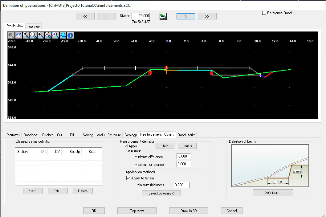
Designate Polylines: For the case that in top view the polylines indicate the reinforcement areas, selecting this button then said polylines, will automatically insert the reinforcement in the corresponding stations according to the definition specified.
Definition of Berms
In this section we define the slope existing beneath the natural terrain in the case of fill, also called berms.
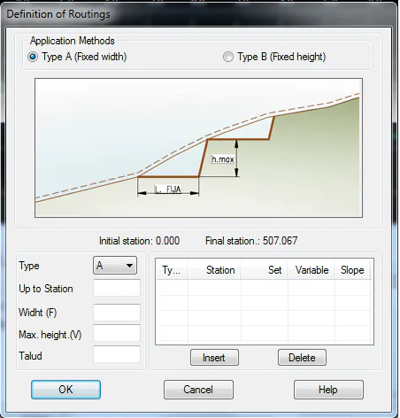
Application Methods: It is possible to apply two different types of berm:
Type A: In this case the width of the berm, that is the horizontal section is fixed, but the step height is variable.
Type B: In this case on the other hand, the height of the step is fixed, and the width of the flat surface is variable.
Up to Station: Station up to which the berm is defined.
Width: Width of the step of the berm or berm. This will be fixed or variable depending on the type of berm selected.
Height: Height of step. This value will likely depend on the berm type applied.
The Insert and Delete buttons are used to control the different berm types to introduce in a particular road.
Road Marks
In this option we have the possibility of assigning the road marks to the elements of the road.
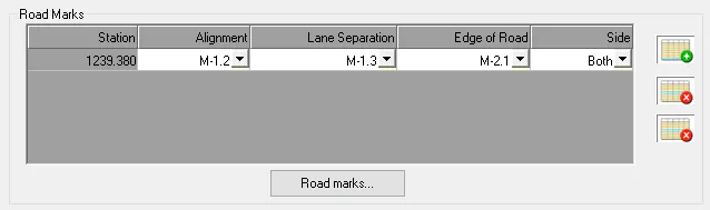
Like the previous elements, they are defined by pks, indicating for each of them the associated line type. In the image we can see a road marking assignment up to pk 507.067.
For each element of the road, Alignment, Lane Separation and Edge of Road we have the possibility to assign a certain road mark. Likewise, in the Side column, we specify the application side of the road marking.
Road marks: We configure the different road markings available. For more details consult the Customization Manual, in the Horizontal Alignments section.