
tcpMDT
[PRO] Ditch Library - MDT26

Ditch Library
 | Command to execute in the CAD |
|---|---|
Vertical menu | MDT26 > Templates > Ditch Library |
Ribbon menu | Templates > Library > Ditches |
Command line |
This command is used to define the ditches we will be working with. Any number of ditches may be defined, though it is not necessary to define them from this option as the Template Definitions command gives the option to create a new ditch if it is required.
When the command is executed, a window is displayed to create, modify, or delete the different ditches the program is working with by default. The ditches defined in these libraries will be added by default in the creation of the template file.
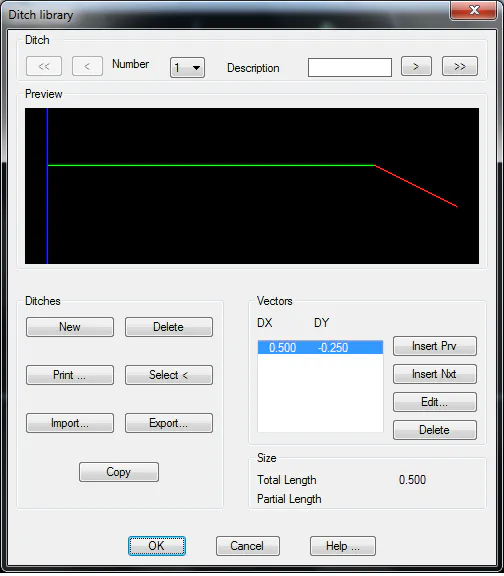
There are three sections:
Ditch: Buttons for moving forward and backward across the entire library of defined ditches.
Ditches: Set of buttons for defining or deleting the existing ditches.
New: Creates a new ditch.
Delete: Eliminates the current ditch.
Print: Prints the list of ditches with their vectors.
Select: Used to graphically select a ditch which has been previously drawn with an AutoCAD polyline.
Import: Imports the ditches from a file.
Export: Exports the ditches from a file.
Copy: Copies the current ditch to a new file.
Vectors: Set of vectors comprising the ditch, with the corresponding buttons for inserting, editing and deleting them.
When any of these vector-editing buttons is selected (Insert Prv., *Insert Nxt., Edit* ) the following window is displayed for specifying the X and Y displacement that the vector the ditch being edited will have.
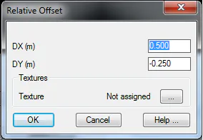
It is important to highlight that the value of the X increment cannot be zero or negative. In other words, vectors always have to travel away from the horizontal alignment. Should a vertical jump need to be entered, a small value can be entered (such as 0.01 or 0.001), which will have practically no effect on the calculations.
In the Textures, the texture associated to each of the vectors can optionally be set This option is used to give a more realistic appearance to the 3D representation commands available in the Maps option. If textures are not assigned, the program will automatically apply a texture when the above-mentioned commands are executed.